TIP36C PNP Transistor (100 V, 25 A) – TO‑247
Description
The TIP36C is a high‑power PNP bipolar junction transistor (BJT) in a TO‑247‑3 through‑hole package. Rated for up to 100 V and 25 A, it is well suited for power amplifier and switching applications due to its low collector‑emitter saturation voltage and high current handling capability.
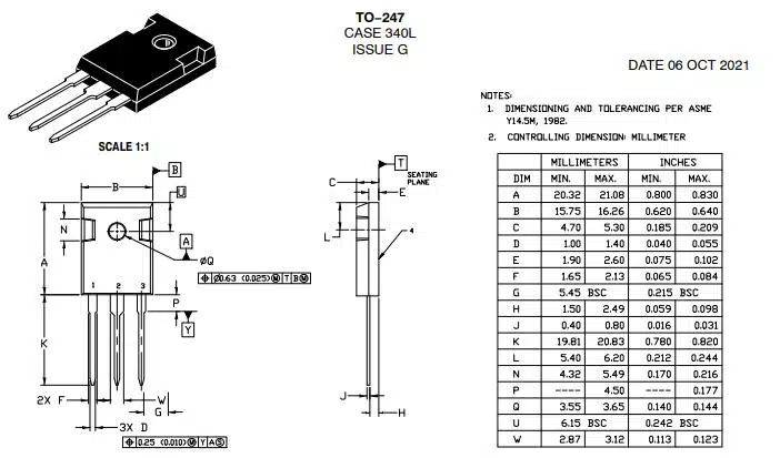
Pin‑Out & Mechanical Dimensions
In the TO‑247 package, the pin configuration (viewed from front, pins downward) is:
| Pin | Name | Function |
|---|---|---|
| 1 | Base | Controls transistor switching |
| 2 | Collector | Main current input (heat‑sink tab is also collector) |
| 3 | Emitter | Main current output |
The tab on the package is connected to the collector terminal.
Absolute Maximum Ratings
| Parameter | Value | Note |
|---|---|---|
| Collector‑Emitter Voltage (VCE) | 100 V | Maximum reverse voltage |
| Collector Current (IC) | 25 A | Continuous |
| Peak Collector Current (ICM) | Approx. 40 A | Short pulses |
| Power Dissipation (PC) | 125 W | With adequate heatsinking |
| Transition Frequency (fT) | 3 MHz | Gain‑bandwidth product |
| Operating Temperature (TJ) | –65 °C to +150 °C | Junction |
Source data synthesised from multiple specifications.
Key Electrical Characteristics
- Low leakage current: ICEO ≈ 1 mA (at VCE = –30 V / –60 V)
- DC current gain (hFE): typ. 25 at IC = –1.5 A; drops to min. 10 at IC = –15 A
- Saturation voltage VCE(sat): approx. 1.8 V (IB=1.5 A, Iₙ=15 A); up to 4 V at IC=25 A, IB=5 A
- Base‑Emitter ON voltage VBE(on): ≈ 2.3 V at 15 A; up to 5 V at 25 A
- Switching times: ton ≈ 1.1 µs; toff ≈ 0.8 µs (resistive‑load, 25 °C case)
Usage Tips & Setup
- Use a substantial heatsink—thermal resistance junction‑to‑case is as low as 1 °C/W, but proper heatsinking is essential for sustaining high current operation.
- Ensure base drive can supply sufficient current (e.g. up to 5 A) to fully saturate the transistor.
- For switching circuits, include a base resistor and consider using a base‑emitter resistor for faster turn‑off.
- Keep operating voltages and currents well below absolute maximums (e.g. ≤ 80 V, ≤ 20 A) to improve reliability.
- Mount on an electrically isolated but thermally conductive pad if collector tab must not be connected to chassis.
Troubleshooting Common Issues
- Overheating / thermal shutdown: Check heatsink mounting, thermal compound, and consider derating load.
- Unexpected saturation voltage or heating: Verify correct base drive current; insufficient base current leads to higher VCE(sat).
- Leakage at high voltage: Elevated leakage suggests possible device damage—replace the transistor.
- Slow switching: Add base‑emitter resistor (e.g. 10 Ω) to speed turn‑off.
Frequently Asked Questions
- What is the complementary NPN transistor?
- The direct complementary NPN device to TIP36C is the TIP35C.
- Is this suitable for audio amplifier output stages?
- Yes—TIP36C is commonly used in power amplifier and switching circuits that require high current and voltage ratings.
- Can it handle pulse currents higher than 25 A?
- Short peak currents up to ~40 A are acceptable if pulses are brief and heatsinking adequate.