16‑Channel Capacitive Touch Keypad – TTP229 User’s Guide
1. Overview
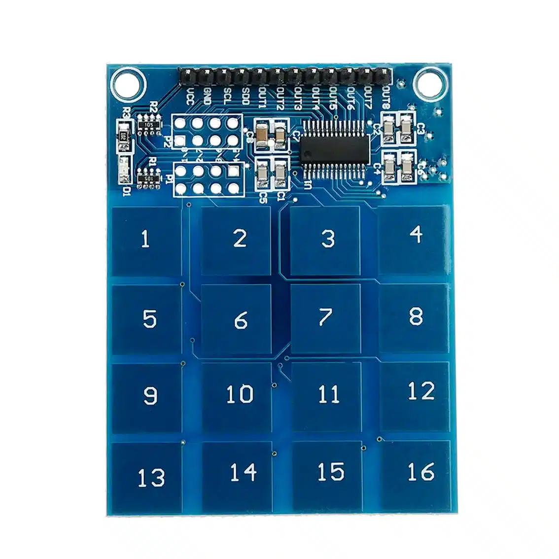
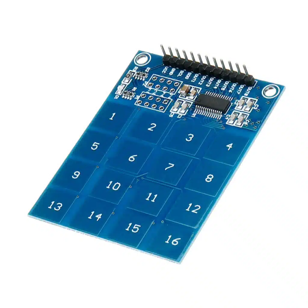
The TTP229 module is a capacitive touch sensor with 16 independent touch pads arranged in a 4×4 grid. It replaces mechanical buttons with touch detection, making it ideal for sleek, modern input systems.
- Keys: 16 touch pads (
1–16) - Interface: Multiple output modes (direct OUT pins or serial interface)
- Applications: Keyboards, menu navigation, PIN entry, DIY controllers, interactive projects
2. Pinout (Typical)
The module usually provides two modes:
Direct Output Mode (16 pins)
- VCC → Power supply (2.4–5.5 VDC)
- GND → Ground
- OUT1–OUT16 → Digital outputs, each goes HIGH when its pad is touched
Serial Output Mode (2‑wire interface)
- VCC → Power supply
- GND → Ground
- SCL → Clock line
- SDO → Data line (serial output of key states)
Many TTP229 boards allow you to configure between 16‑pin parallel mode or 2‑wire serial mode using solder jumpers.
On the TTP229 16‑channel capacitive touch keypad, the P1 and P2 ports are configuration jumpers/pads used to set how the chip behaves. They don’t connect to the microcontroller directly — instead, they let you change the operating mode of the keypad.
P1 and P2 Port Functions
- P1 (Mode Select 1)
- Determines whether the keypad outputs are in direct 16‑pin parallel mode (OUT1–OUT16) or in serial 2‑wire mode (SCL/SDO).
- In serial mode, you only need 2 pins on your microcontroller, which is useful if you’re short on I/O.
- P2 (Mode Select 2)
- Configures detection behavior:
- Single‑key mode → Only one key can be active at a time (common for PIN entry).
- Multi‑key mode → Multiple keys can be pressed and detected simultaneously (useful for custom keyboards or controllers).
- Configures detection behavior:
How to Use Them
- They are usually solder jumpers or pads on the PCB.
- By shorting or leaving them open, you select the desired mode.
- Example:
- P1 open, P2 open → 16‑pin direct output, single‑key mode.
- P1 shorted, P2 open → Serial output, single‑key mode.
- P1 shorted, P2 shorted → Serial output, multi‑key mode.
If you’re using Arduino or ESP32, serial mode (P1 enabled) is often easier because it reduces wiring from 16 pins down to just 2. But if you want fast, simple detection without extra code, direct mode (P1 disabled) gives you one pin per key.
So in short:
- P1 = Output mode (parallel vs serial)
- P2 = Key detection mode (single vs multi‑key)
3. How It Works
- Each pad senses the change in capacitance when touched.
- The TTP229 IC processes signals and outputs either:
- Direct digital HIGH/LOW on OUT pins, or
- Serial data stream with key states.
- Supports single‑key or multi‑key detection, depending on jumper settings.
4. Wiring to Arduino UNO (Serial Mode Example)
TTP229 Pin → Arduino Pin
VCC → 5V
GND → GND
SCL → D2
SDO → D3
5. Arduino Code Example (Serial Mode)
#define SCL 2
#define SDO 3

void setup() {
  pinMode(SCL, OUTPUT);
  pinMode(SDO, INPUT);
  Serial.begin(9600);
}

void loop() {
  digitalWrite(SCL, LOW);
  delayMicroseconds(2);
  digitalWrite(SCL, HIGH);
  delayMicroseconds(2);

  for (int i = 0; i < 16; i++) {
    digitalWrite(SCL, LOW);
    delayMicroseconds(2);
    int keyState = digitalRead(SDO);
    if (keyState == 0) {
      Serial.print("Key ");
      Serial.print(i+1);
      Serial.println(" touched");
    }
    digitalWrite(SCL, HIGH);
    delayMicroseconds(2);
  }
}
6. Applications
- Security systems: Touch‑based PIN entry with up to 16 digits
- Menu navigation: Complex option control for LCD interfaces
- DIY controllers: Gamepads or custom input devices
- Smart appliances: Touch panels for lighting or home automation
7. Tips & Best Practices
- Keep sensor pads clean and dry for reliable detection.
- If using serial mode, fewer pins are needed (ideal for Arduino Nano/ESP32).
- Pads can be hidden behind thin plastic or acrylic for a sealed touch interface.
- Avoid long wires on SCL/SDO to reduce noise.