28BYJ‑48 Stepper Motor + ULN2003 Driver Board User’s Guide
User’s Guide
28BYJ‑48 Stepper Motor + ULN2003 Driver Board
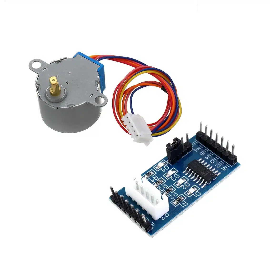
1. Product Overview
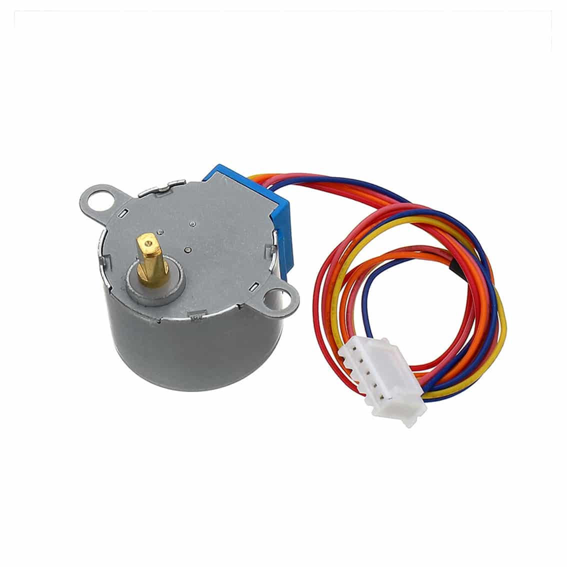
- 28BYJ‑48 Stepper Motor
- Type: Unipolar stepper motor
- Voltage: 5V DC (common version)
- Steps per revolution: ~2048 (with internal gear reduction)
- Wires: 5 (Red, Orange, Yellow, Blue, Pink)
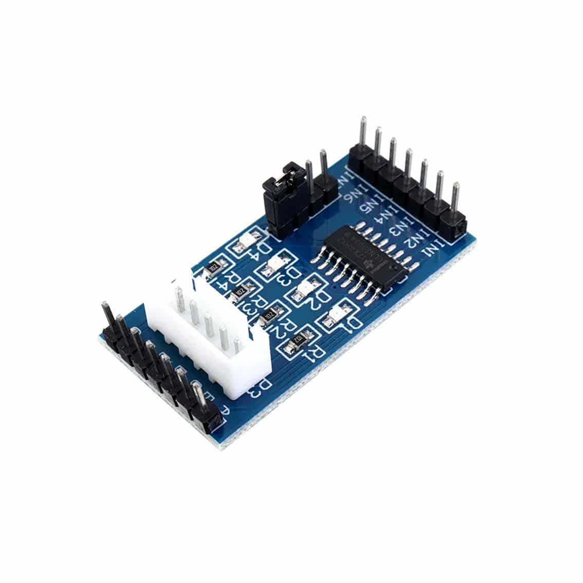
- ULN2003 Driver Board
- IC: ULN2003A (Darlington transistor array)
- Inputs: IN1–IN4 (logic signals from microcontroller to motor driver, other IN5 – IN7 inputs exposed on the other header pins)
- Outputs: Drive motor coils via white connector
- Power: VCC (5V), GND
2. Pinout
ULN2003 Driver Board
| Pin | Function |
|---|---|
| IN1–IN4 | Control inputs from Arduino/ESP32/etc. |
| VCC | +5V supply |
| GND | Ground |
| Motor Connector | White socket for 28BYJ‑48 motor wires |
28BYJ‑48 Motor Wire Colors
| Wire Color | Coil |
|---|---|
| Red | Common (VCC) |
| Orange | Coil A |
| Yellow | Coil B |
| Pink | Coil C |
| Blue | Coil D |
3. How It Works
- The ULN2003 board takes low‑power signals from a microcontroller and safely drives the motor coils.
- The motor rotates step by step when IN1–IN4 are activated in sequence.
- By changing the sequence and timing, you control direction and speed.
4. Wiring Guide (Arduino Example)
- Connect VCC on ULN2003 → Arduino 5V.
- Connect GND on ULN2003 → Arduino GND.
- Connect IN1–IN4 → Arduino digital pins (e.g., D8–D11).
- Plug the motor’s white connector into the ULN2003 board.
5. Example Arduino Code
#include <Stepper.h>

const int stepsPerRevolution = 2048; // 28BYJ-48 with gear reduction
Stepper myStepper(stepsPerRevolution, 8, 10, 9, 11);

void setup() {
  myStepper.setSpeed(10); // RPM
}

void loop() {
  myStepper.step(stepsPerRevolution); // one full rotation clockwise
  delay(1000);
  myStepper.step(-stepsPerRevolution); // one full rotation counterclockwise
  delay(1000);
}
6. Applications
- Educational kits: Demonstrating stepper motor control.
- Robotics: Precise positioning for arms or wheels.
- Automation: Small actuators, dials, or indicators.
- DIY projects: Rotating displays, camera sliders, or tuning knobs.
7. Best Practices
- Always use 5V regulated supply for the motor.
- Avoid driving directly from Arduino pins — always use the ULN2003 board.
- Stepper motors draw current even when stationary; disconnect power if not in use.
- For smoother motion, use half‑step or microstepping sequences.
8. Miscellaneous Info
- Standard ULN2003 boards for the 28BYJ‑48 stepper usually expose IN1–IN4, because the motor only needs 4 control signals.
- However, the ULN2003 chip itself has 7 Darlington transistor channels. That means it can drive up to 7 separate loads (LEDs, relays, coils, etc.).
- Some board designs break out all 7 inputs (IN1–IN7) and their corresponding outputs, even though the 28BYJ‑48 motor only uses 4.
How It Relates to Your Motor
- For the 28BYJ‑48 stepper motor, you only need IN1–IN4. These connect to the motor’s 4 coils via the white connector.
- The extra inputs (IN5–IN7) are not used for this motor. They’re just exposed in case you want to drive other devices with the same board.