4‑Channel Capacitive Touch Keypad (TTP224) User’s Guide
1. Overview
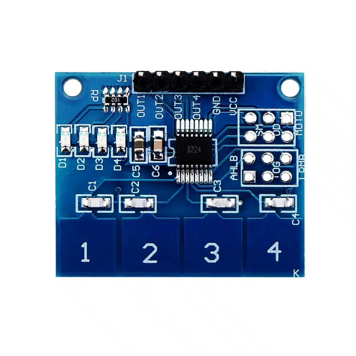
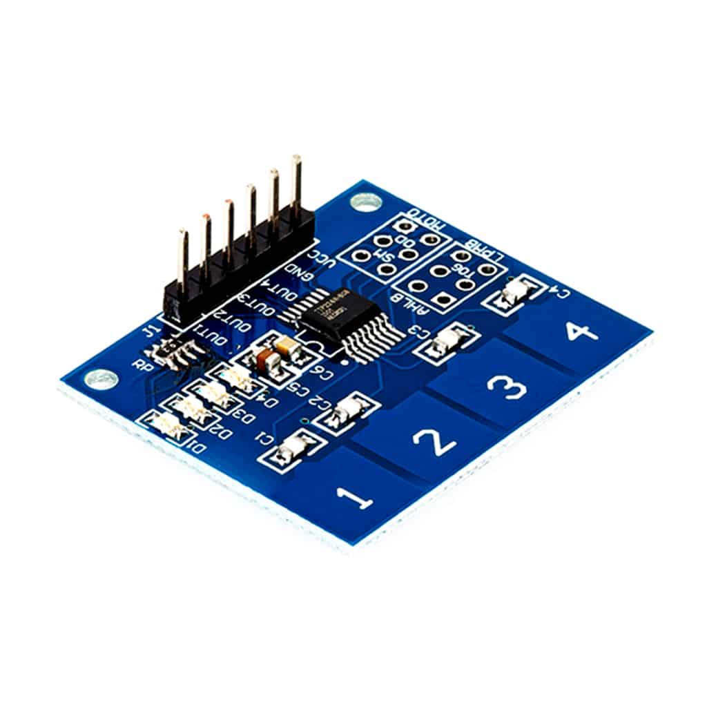
The TTP224 module is a capacitive touch sensor with 4 independent touch pads. Instead of mechanical buttons, it detects finger touches on conductive pads, making it ideal for sleek, modern input interfaces.
- Keys: 4 touch pads (
1,2,3,4) - Interface: 6‑pin header (
VCC,GND,OUT1–OUT4) - Applications: Touch‑based switches, menu navigation, mode selection, DIY controllers, interactive projects
2. Pinout
| Pin | Function | Notes |
|---|---|---|
| VCC | Power supply (2.4–5.5 VDC) | Works with Arduino 5 V or ESP32 3.3 V |
| GND | Ground | Common ground with microcontroller |
| OUT1 | Digital output for Pad 1 | HIGH when touched |
| OUT2 | Digital output for Pad 2 | HIGH when touched |
| OUT3 | Digital output for Pad 3 | HIGH when touched |
| OUT4 | Digital output for Pad 4 | HIGH when touched |
The extra labeled ports like AHLB and the MOTO 6‑pin header are configuration and mode‑setting connections rather than direct inputs/outputs. They let you fine‑tune how the sensor behaves:
AHLB Port
- AHLB = Active High / Low & Behavior control
- This jumper/pad determines whether the OUT pins go HIGH or LOW when touched.
- By default, most boards output HIGH on touch.
- If you bridge or reconfigure AHLB, you can invert the logic so the outputs go LOW on touch.
- Useful if your circuit expects active‑low signals (e.g., driving LEDs or interfacing with certain logic ICs).
MOTO 6‑Pin Header
- This is a configuration/programming header provided by the TTP224 design.
- It exposes internal pins of the IC for advanced settings such as:
- Output mode selection (momentary vs toggle latch)
- Sensitivity adjustment (how easily the pads detect touch)
- Multi‑key vs single‑key detection (whether multiple pads can be active at once)
- Timing options (response speed, auto‑repeat behavior)
- On most breakout boards, these pins are not used in basic Arduino projects — they’re left unconnected unless you want to customize the sensor’s behavior at the hardware level.
Practical Use
- For everyday Arduino/ESP projects, you only need VCC, GND, OUT1–OUT4.
- AHLB is handy if you want inverted logic.
- MOTO header is for advanced users who want to tweak the IC’s internal configuration — most hobbyists leave it alone.
So in short:
- AHLB = output polarity control (active high vs active low)
- MOTO 6‑pin = advanced configuration header for sensitivity, mode, and latch/toggle options
3. How It Works
- Each pad senses the change in capacitance when a finger touches it.
- The IC (TTP224) processes the signal and outputs a digital HIGH on the corresponding OUT pin.
- No mechanical wear → longer lifespan and smoother operation.
4. Wiring to Arduino UNO (Example)
TTP224 Pin → Arduino Pin
VCC → 5V
GND → GND
OUT1 → D2
OUT2 → D3
OUT3 → D4
OUT4 → D5
5. Arduino Code Example
int touchPins[4] = {2, 3, 4, 5};

void setup() {
  Serial.begin(9600);
  for (int i = 0; i < 4; i++) {
    pinMode(touchPins[i], INPUT);
  }
}

void loop() {
  for (int i = 0; i < 4; i++) {
    if (digitalRead(touchPins[i]) == HIGH) {
      Serial.print("Pad ");
      Serial.print(i+1);
      Serial.println(" touched");
    }
  }
}
6. Applications
- Security systems: Touch‑based PIN entry
- Menu navigation: Sleek alternative to mechanical buttons
- Lighting control: Touch switches for lamps or appliances
- DIY controllers: Interactive touch input for games or projects
7. Tips & Best Practices
- Keep sensor pads clean and dry for reliable detection.
- Avoid long wires on OUT pins to reduce noise.
- Works best with finger touch; gloves may reduce sensitivity.
- Can be mounted behind thin non‑metallic surfaces (plastic, acrylic) for hidden touch controls.