4×4 Matrix Keypad Keyboard Module (16 Keys) User’s Guide
1. Overview
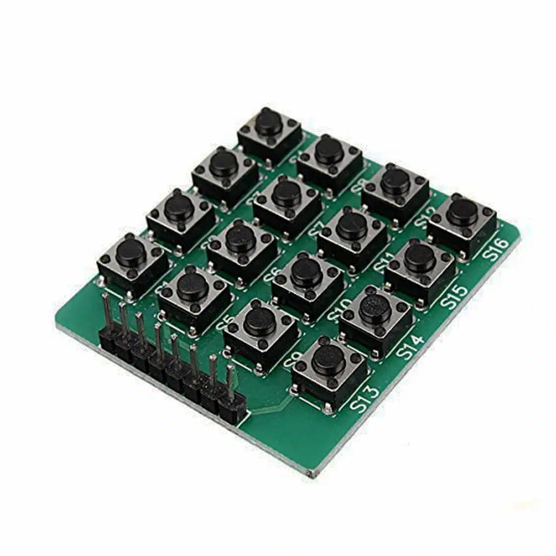
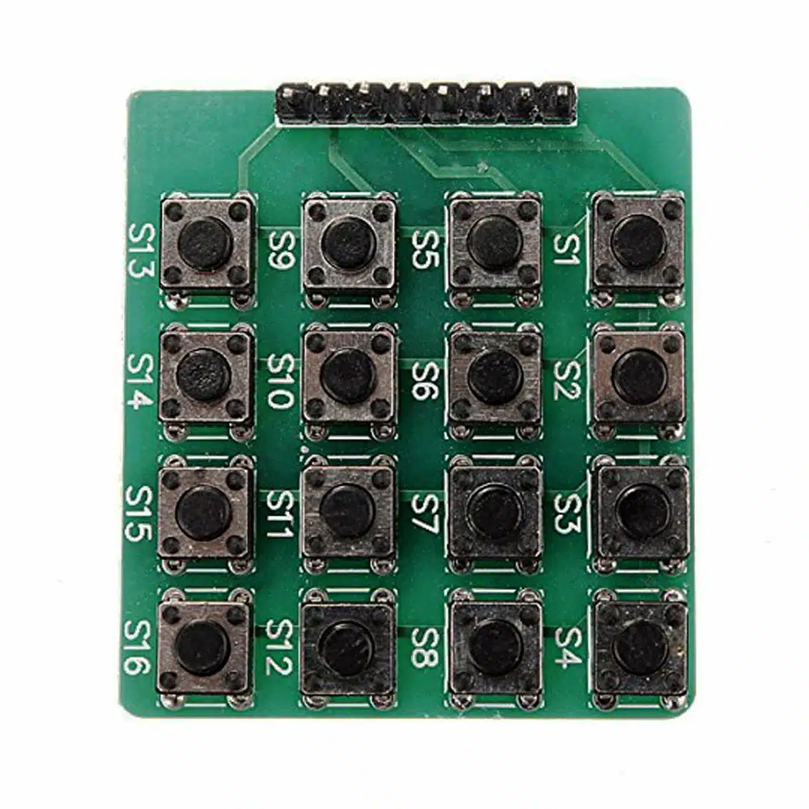
The 4×4 Matrix Keypad Module is a compact input device with 16 push buttons arranged in 4 rows × 4 columns. Unlike membrane keypads, this module uses individual tactile switches soldered onto a PCB, making it more durable and responsive.
- Keys: S1-S16 push-button mechanical tact switches (N.O.)
- Connector: 8‑pin header (4 row lines + 4 column lines)
- Applications: PIN entry, calculators, menu navigation, robotics control panels, DIY electronics kits.
2. Pinout (8‑Pin Header)
The module exposes 8 pins for interfacing:
| Pin | Function | Description |
|---|---|---|
| 1–4 | R1–R4 | Row lines |
| 5–8 | C1–C4 | Column lines |
Pin order may vary depending on the manufacturer. Use a continuity test if needed.
3. Working Principle
- Each button connects a row line to a column line when pressed.
- The microcontroller scans rows and columns to detect which button is pressed.
- Example: Pressing
5connects Row 2 with Column 2.
4. Wiring Example (Arduino UNO)
Keypad Pin → Arduino Pin
R1 → D2
R2 → D3
R3 → D4
R4 → D5
C1 → D6
C2 → D7
C3 → D8
C4 → D9
5. Arduino Code Example
#include <Keypad.h>

const byte ROWS = 4; // four rows
const byte COLS = 4; // four columns

char keys[ROWS][COLS] = {
  {'1','2','3','A'},
  {'4','5','6','B'},
  {'7','8','9','C'},
  {'*','0','#','D'}
};

byte rowPins[ROWS] = {2, 3, 4, 5}; // R1–R4
byte colPins[COLS] = {6, 7, 8, 9}; // C1–C4

Keypad keypad = Keypad(makeKeymap(keys), rowPins, colPins, ROWS, COLS);

void setup() {
  Serial.begin(9600);
}

void loop() {
  char key = keypad.getKey();
  if (key) {
    Serial.println(key);
  }
}
6. Applications
- Numeric entry for calculators or PIN systems
- Menu navigation in embedded projects
- Security systems (password input)
- Educational kits (matrix scanning demonstration)
- DIY controllers for robotics or games
7. Best Practices
- Use the Keypad library for reliable scanning and debouncing.
- Ensure solid solder joints on the header pins for durability.
- Mount the module on a panel or enclosure for stability.
- Keep wiring short to minimize signal noise.
- For ESP32/ESP8266, check pin availability before wiring.