
A4988 Stepper Motor Driver Breakout Board – User’s Guide
Overview
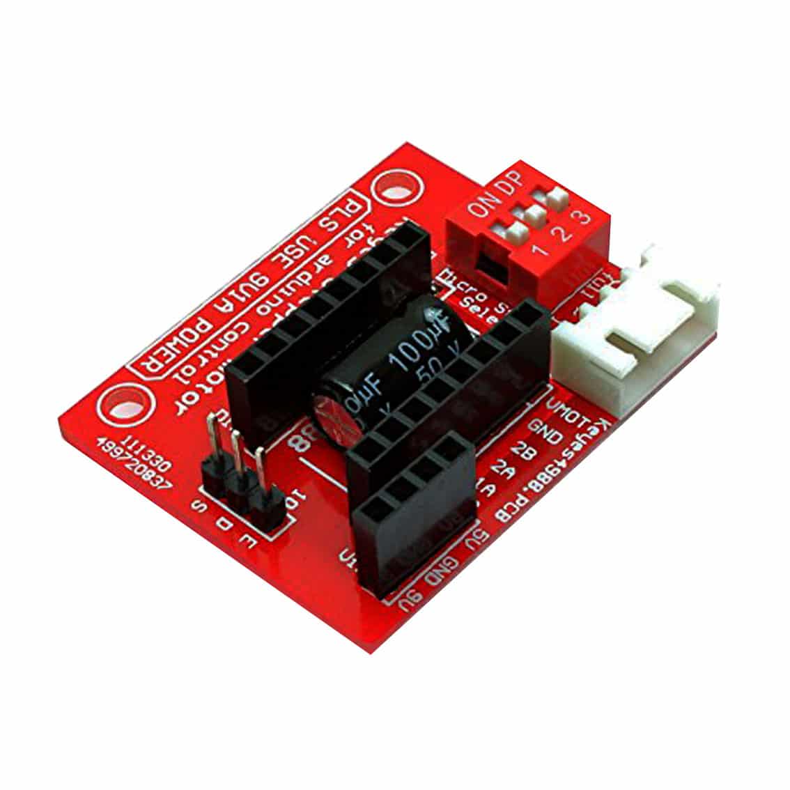
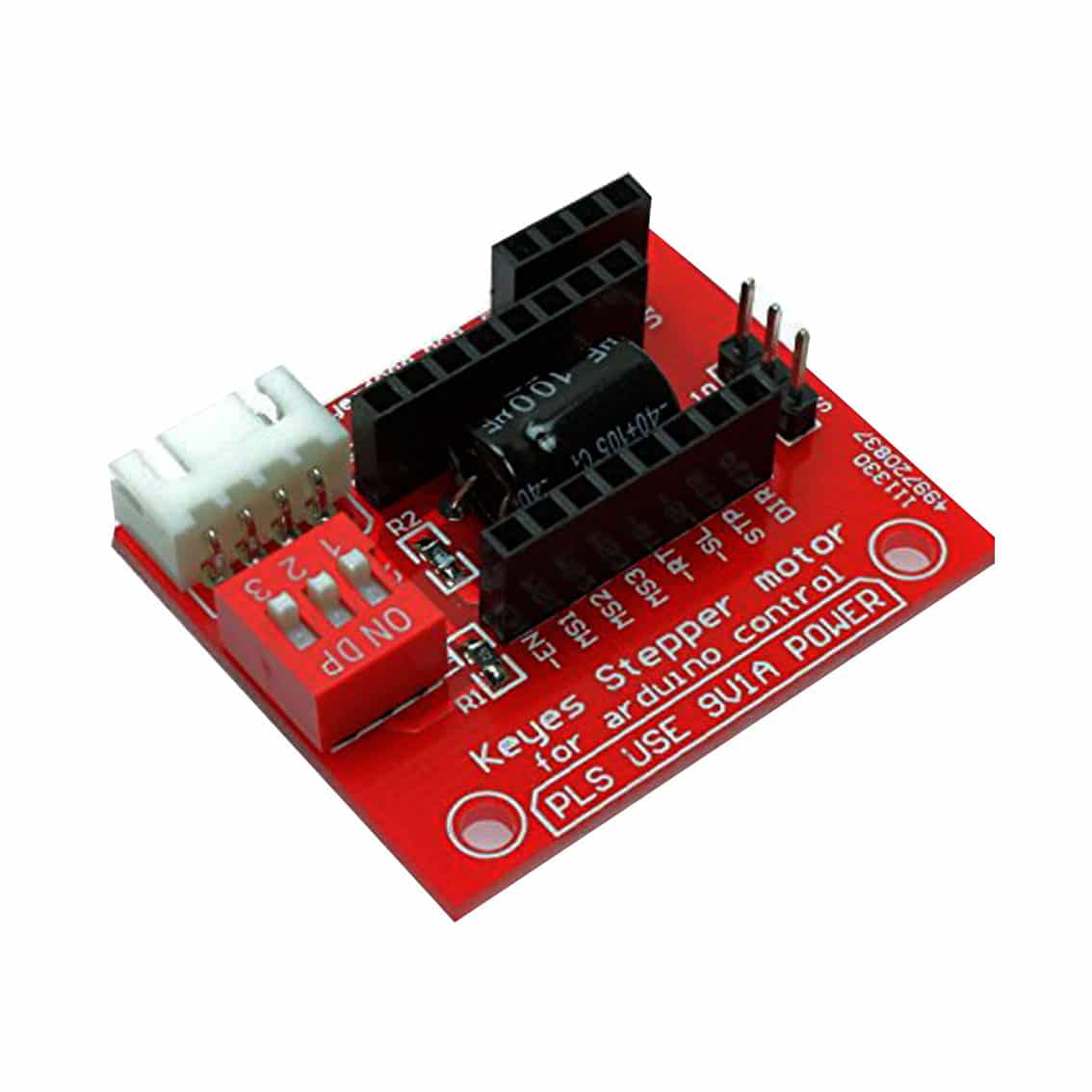
The A4988 breakout board is a microstepping driver for bipolar stepper motors. It supports full, half, quarter, eighth, and sixteenth steps, and can drive up to 2 A per coil with proper cooling. It’s widely used in 3D printers, CNC machines, and robotics.
Pinout
Left Side – Control Pins
| Pin | Function |
|---|---|
| ENABLE | Active LOW. Pull LOW to enable motor outputs. |
| MS1, MS2, MS3 | Microstep resolution selection. |
| RESET | Active LOW reset. Tie HIGH (or to SLEEP) if unused. |
| SLEEP | Active LOW sleep mode. Tie HIGH to keep driver active. |
| STEP | Pulse input. Each rising edge = one step. |
| DIR | Direction input. HIGH = one direction, LOW = opposite. |
Right Side – Power & Motor Pins
| Pin | Function |
|---|---|
| VMOTOR | Motor power supply (8–35 V). |
| GND (Motor) | Motor ground. |
| 2B, 2A | Motor coil 2 outputs. |
| 1B, 1A | Motor coil 1 outputs. |
| VDD | Logic supply (3–5.5 V). |
| GND (Logic) | Logic ground. |
Microstepping Modes
| MS1 | MS2 | MS3 | Step Mode |
|---|---|---|---|
| LOW | LOW | LOW | Full step |
| HIGH | LOW | LOW | Half step |
| LOW | HIGH | LOW | Quarter step |
| HIGH | HIGH | LOW | Eighth step |
| HIGH | HIGH | HIGH | Sixteenth step |
Example Arduino Wiring
int stepPin = 3;
int dirPin = 4;

void setup() {
  pinMode(stepPin, OUTPUT);
  pinMode(dirPin, OUTPUT);
  digitalWrite(dirPin, HIGH); // set direction
}

void loop() {
  // Rotate motor 200 steps
  for(int i=0; i<200; i++) {
    digitalWrite(stepPin, HIGH);
    delayMicroseconds(800);
    digitalWrite(stepPin, LOW);
    delayMicroseconds(800);
  }
  delay(1000);
  digitalWrite(dirPin, LOW); // reverse direction
}
Applications
- 3D printers (extruder, axis control)
- CNC machines
- Robotics (precise positioning)
- Educational kits for stepper motor learning
Best Practices
- Place a large electrolytic capacitor (≥100 µF) across VMOTOR and GND to absorb voltage spikes.
- Tie RESET and SLEEP together if you don’t need separate control.
- Use a heat sink if driving >1 A per coil.
- Adjust the current limit via the onboard potentiometer before connecting the motor.
- Never connect/disconnect motors while powered.