
BTS7960 43A Dual H‑Bridge Motor Driver User’s Guide
Overview
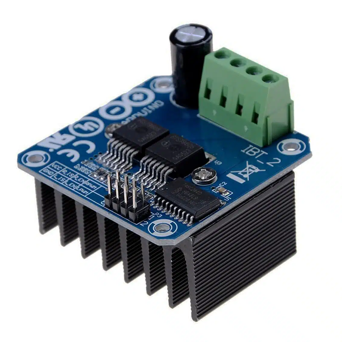
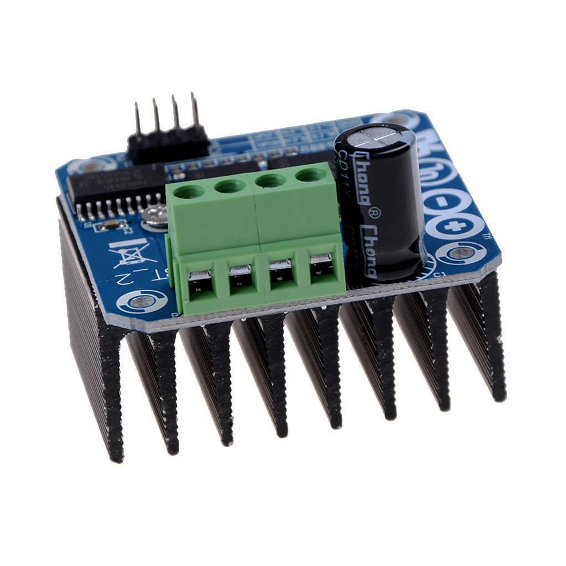
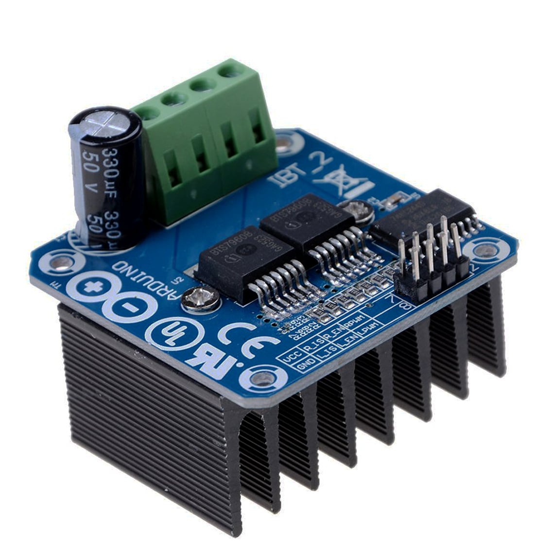
The BTS7960 module is a high‑power motor driver based on Infineon’s BTS7960 half‑bridge chips. It’s designed to control large DC motors with PWM speed control and bidirectional drive.
- Voltage range: 6 V – 27 V
- Peak current: up to 43 A (continuous ~20–25 A with cooling)
- Logic level: 5 V (Arduino, STM32, ESP32 compatible)
- Applications: robotics, e‑mobility, pumps, actuators, heavy DC loads
Pinout & Connections
| Pin | Function | Notes |
|---|---|---|
| VCC | Logic supply (5 V) | From Arduino/MCU |
| GND | Ground | Common ground with MCU & motor supply |
| RPWM | Right PWM input | Controls forward speed |
| LPWM | Left PWM input | Controls reverse speed |
| R_EN | Right enable | Tie HIGH to enable |
| L_EN | Left enable | Tie HIGH to enable |
| R_IS | Right current sense | Analog output (optional) |
| L_IS | Left current sense | Analog output (optional) |
| Motor+ / Motor‑ | Motor terminals | Connect DC motor |
| VCC Motor | Motor supply | 6–27 V, high‑current capable |
Control Logic
- Forward motion:
RPWM = PWM signalLPWM = LOW
- Reverse motion:
LPWM = PWM signalRPWM = LOW
- Stop:
- Both PWM inputs LOW
- Enable pins:
- Keep
R_ENandL_ENHIGH for normal operation
- Keep
Example Arduino Wiring
int RPWM = 9;   // Forward PWM pin
int LPWM = 10;  // Reverse PWM pin
int REN  = 7;   // Right enable
int LEN  = 8;   // Left enable

void setup() {
  pinMode(RPWM, OUTPUT);
  pinMode(LPWM, OUTPUT);
  pinMode(REN, OUTPUT);
  pinMode(LEN, OUTPUT);
  digitalWrite(REN, HIGH);
  digitalWrite(LEN, HIGH);
}

void loop() {
  // Forward at 50% speed
  analogWrite(RPWM, 128);
  analogWrite(LPWM, 0);
  delay(2000);

  // Reverse at 75% speed
  analogWrite(RPWM, 0);
  analogWrite(LPWM, 192);
  delay(2000);

  // Stop
  analogWrite(RPWM, 0);
  analogWrite(LPWM, 0);
  delay(2000);
}
Applications
- Heavy robotics (drive motors, tracked vehicles)
- Electric scooters or carts (with proper safety circuits)
- Industrial pumps, fans, actuators
- High‑power DC motor experiments
Best Practices
- Cooling: Always use a heatsink/fan for >20 A loads.
- Power supply: Ensure motor supply can handle surge currents.
- Wiring: Use thick gauge wires for motor terminals.
- Protection: Add fuses or circuit breakers for safety.
- Not for steppers: Despite “stepper” in some listings, this module is not suitable for precise stepper motor control. It’s for brushed DC motors.