DRV8825 Stepper Motor Driver Module – User’s Guide
1. Overview
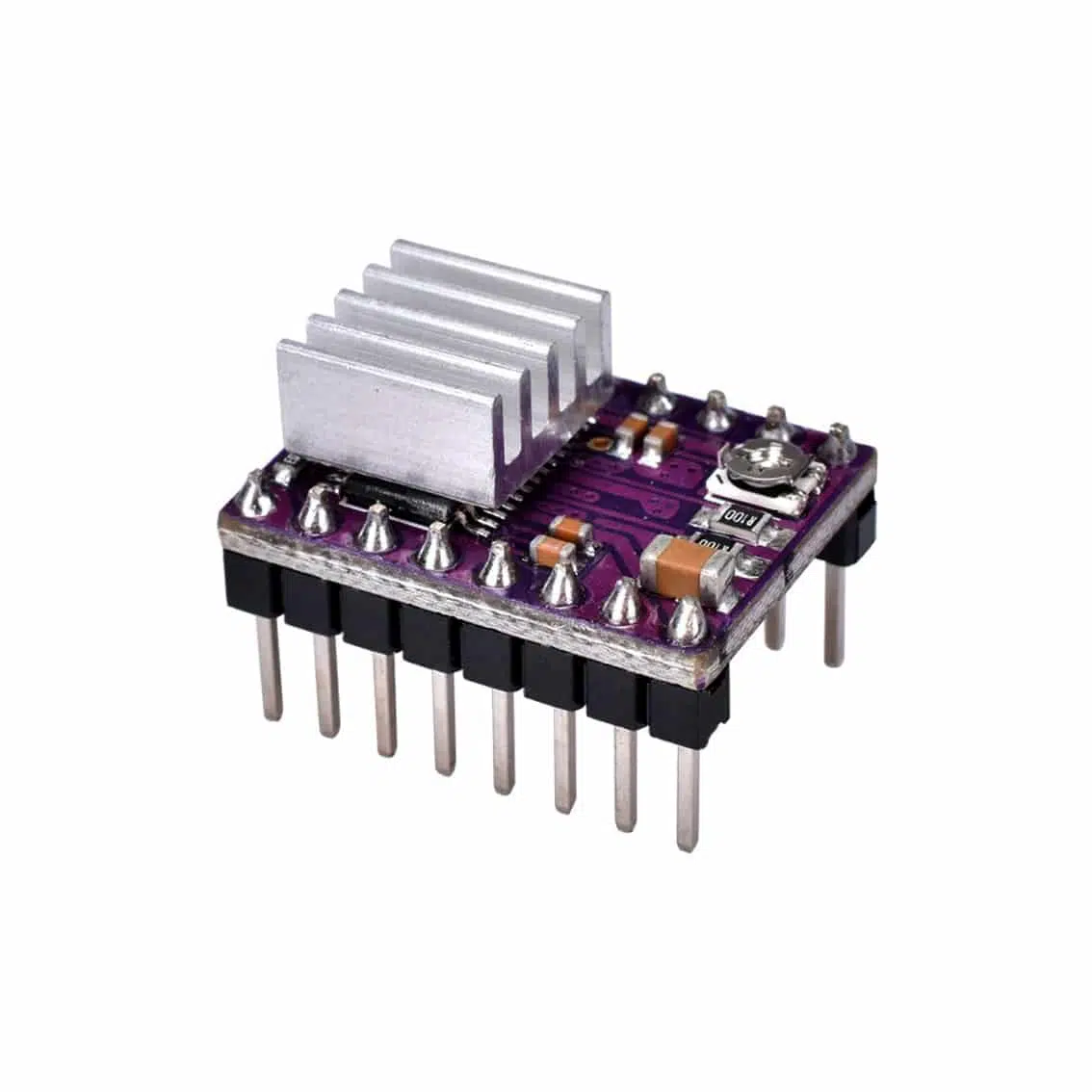
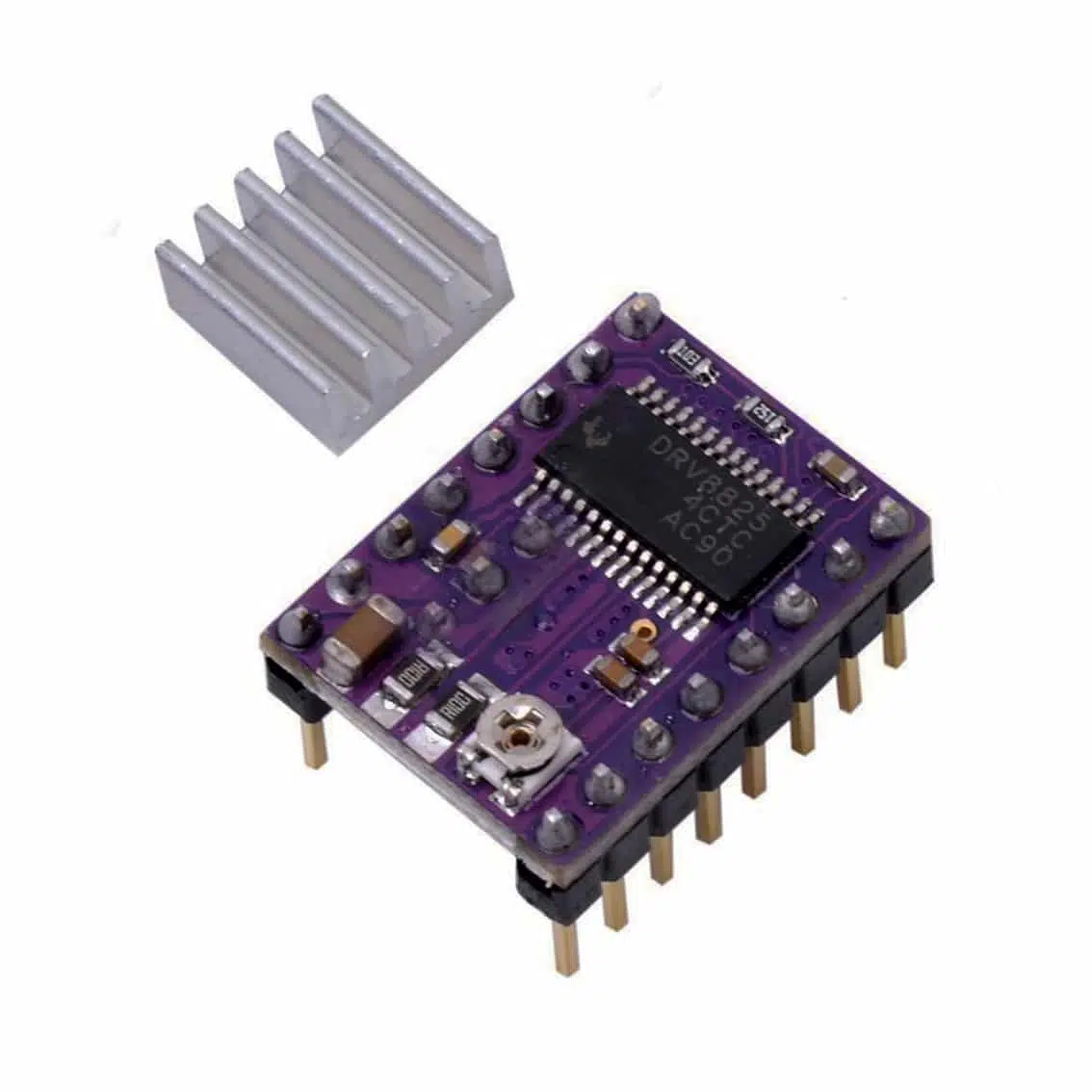
The DRV8825 is a bipolar stepper motor driver with microstepping up to 1/32 step. It comes on a breakout board with a heatsink for cooling. It’s widely used in 3D printers, CNC machines, and robotics.
2. Specifications
- Motor Type: Bipolar stepper motors
- Motor Voltage (VMOT): 8.2–45 V DC
- Logic Voltage (VDD): 3.3–5 V DC
- Current per Phase: Up to 2.5 A (with heatsink/fan)
- Microstepping: Full step to 1/32 step
- Protection: Over-temperature, short-to-ground, undervoltage lockout, fault reporting via FLT pin
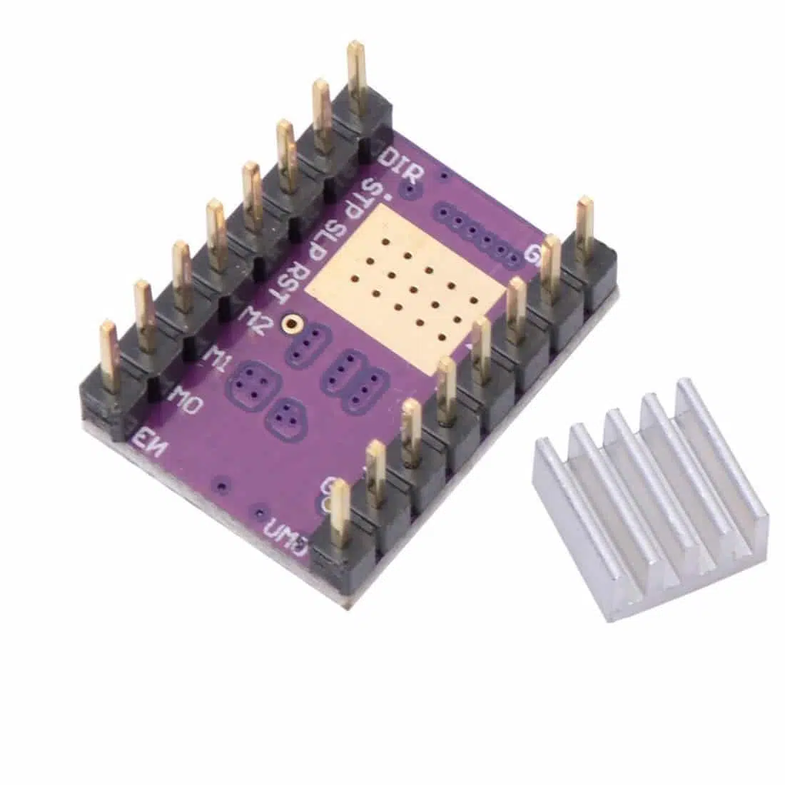
3. Pinout & Connections
Control Pins
| Pin | Function |
|---|---|
| DIR | Direction control |
| STP (STEP) | Step pulse input |
| EN (Enable) | Enable driver (active low) |
| RST (Reset) | Resets driver (active low) |
| SLP (Sleep) | Low-power mode (active low) |
| M0, M1, M2 | Microstep resolution selection |
| FLT (Fault) | Open-drain output, goes LOW when a fault occurs (e.g., overcurrent, thermal shutdown) |
Power & Motor Pins
| Pin | Function |
|---|---|
| VMOT / GND | Motor power supply (8.2–45 V) |
| A1, A2 | Motor coil A |
| B1, B2 | Motor coil B |
| VDD / GND | Logic supply (3.3–5 V) |
4. Microstepping Settings (M0, M1, M2)
| M0 | M1 | M2 | Step Mode |
|---|---|---|---|
| Low | Low | Low | Full step |
| High | Low | Low | 1/2 step |
| Low | High | Low | 1/4 step |
| High | High | Low | 1/8 step |
| Low | Low | High | 1/16 step |
| High | Low | High | 1/32 step |
5. Current Adjustment
- Adjust via the potentiometer.
- Formula:
[ I_{max} = \frac{V_{ref}}{0.5} ] - Example: (V_{ref} = 1.0 , V \Rightarrow I_{max} = 2.0 , A).
- Always set slightly below motor’s rated current.
6. Wiring Example
Controller → DRV8825
- DIR → Arduino pin (e.g., D3)
- STP → Arduino pin (e.g., D2)
- EN → Arduino pin (optional, e.g., D4)
- FLT → Arduino pin (optional, for fault monitoring)
- VDD → 5V
- GND → Arduino GND
Motor → DRV8825
- A1, A2 → Coil A
- B1, B2 → Coil B
Power Supply
- VMOT → 12–24 V DC (recommended)
- GND → Power ground
- Add a 100 µF capacitor across VMOT and GND.
7. Example Arduino Code (with FLT monitoring)
#define STEP_PIN 2
#define DIR_PIN 3
#define EN_PIN 4
#define FLT_PIN 5

void setup() {
  pinMode(STEP_PIN, OUTPUT);
  pinMode(DIR_PIN, OUTPUT);
  pinMode(EN_PIN, OUTPUT);
  pinMode(FLT_PIN, INPUT);
  digitalWrite(EN_PIN, LOW); // Enable driver
  Serial.begin(9600);
}

void loop() {
  if (digitalRead(FLT_PIN) == LOW) {
    Serial.println("Fault detected!");
    // Handle fault (stop motor, reset, etc.)
  } else {
    digitalWrite(DIR_PIN, HIGH); // Set direction
    for (int i = 0; i < 200; i++) {
      digitalWrite(STEP_PIN, HIGH);
      delayMicroseconds(500);
      digitalWrite(STEP_PIN, LOW);
      delayMicroseconds(500);
    }
    delay(1000);
  }
}
8. Applications
- 3D printers (extruder, axis control)
- CNC machines
- Robotics (precise linear/rotary motion)
- Automated positioning systems
9. Best Practices
- Attach heatsink and fan for >1.5 A operation.
- Use capacitor across VMOT/GND.
- Monitor FLT pin for safety.
- Start with low current settings.
- Double-check coil wiring.