
← Back
You are here:
Print
E3F-DS30P1 PNP Photoelectric Proxmity Switch Sensor – Normally Open User’s guide
Last Updated On
0
0
Overview
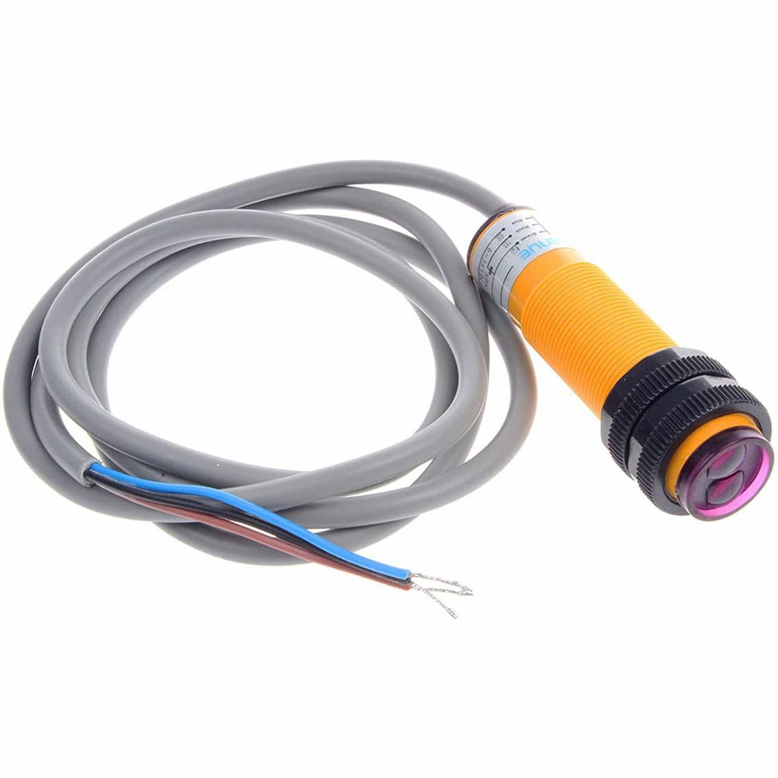
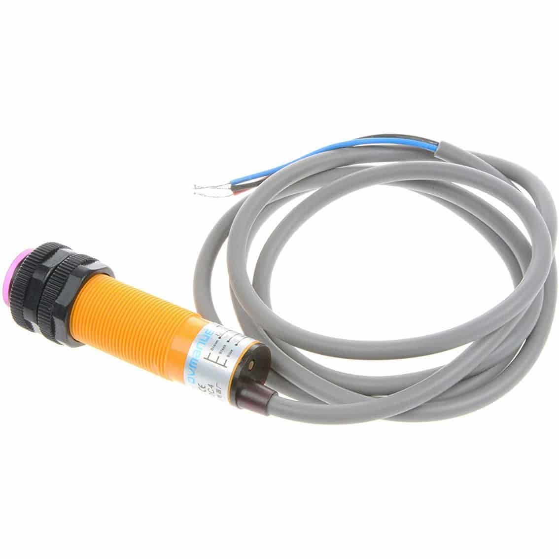
The E3F‑DS30P1 is a cylindrical photoelectric sensor designed for long‑range object detection. It uses infrared light to sense targets and provides a PNP output, Normally Open (NO) configuration. This means the output is inactive until an object is detected, at which point the circuit closes and the output becomes active (connected to +V).
Specifications
- Model: E3F‑DS30P1
- Type: Photoelectric proximity switch
- Output: PNP, Normally Open
- Sensing distance: ~30 cm (depending on target surface)
- Supply voltage: 6–36 V DC
- Wiring: 3‑wire (Brown = V+, Blue = GND, Black = Output)
- Body: Cylindrical, threaded, with adjustable sensitivity ring
Wiring Guide
| Wire Color | Connection | Function |
|---|---|---|
| Brown | +V (6–36 V DC) | Power supply positive |
| Blue | 0 V (Ground) | Power supply negative |
| Black | Output signal | Connect to controller input |
Note: Since it’s PNP NO, the black wire is normally open (inactive). When an object is detected, the black wire is driven high (+V, active).
Installation
- Mounting: Secure the sensor using its threaded body and a bracket.
- Alignment: Aim the lens toward the detection zone.
- Wiring: Connect wires to your PLC, Arduino, or relay module as per the table above.
- Adjustment: Rotate the black sensitivity ring to fine‑tune detection distance.
Operation
- No object detected → Output is open (inactive).
- Object detected → Output closes, driving the black wire high (+V, active).
- Controllers should be configured to read a high signal as “object detected.”
Applications
- Long‑range detection (up to 30 cm)
- Conveyor belt monitoring
- Position sensing in automated machinery
- Robotics and automation projects requiring PNP logic
Safety Notes
- Supply voltage must not exceed 36 V DC.
- Avoid reflective surfaces that may cause false triggers.
- Insulate exposed wires to prevent shorts.
- Test sensor response before integrating into critical systems.
Table of Contents