ISD1820 Voice Recorder Module User Guide
INTRODUCTION:
The Voice Record Module is based on the ISD1820 and is a multiple‐message record/playback device. It module offers true single‐chip voice recording with no‐volatile storage and playback capability for 8 to 20 seconds.
The sample rate can be set as low as 3.2k and allows for a total of 20 seconds of recording.
The module is easy to use with buttons on the board to perform the functions, as well as the option to control with a Microcontroller such as Arduino.
FEATURES:
- Push‐button interface, playback can be edge or level activated
- Automatic power‐down mode
- On‐chip 8Ω speaker driver
- Signal 3V Power Supply
- Can be controlled both manually or by MCU
- Sample rate and duration changeable by replacing a single resistor
- Records up to 20 seconds of audio
- Dimensions: 37 x 54 mm
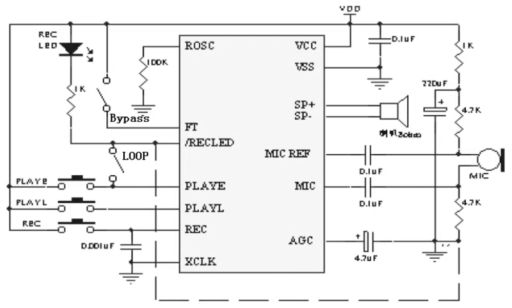
CIRCUIT DIAGRAM:
APPLICATION:
CHANGE LENGTH OF RECORDING:
If you want to change the recording duration, an external resistor is necessary to select the record duration and sampling frequency, which can range from 8 – 20 seconds (4‐12kHz sampling frequency). The module by default has a 100k resistor with a default recording length of 10s.
Refer to the table below on required resistors to modify this:
| ROSC | Duration | Sample Rate | Bandwidth |
|---|---|---|---|
| 80K Ω | 8 Seconds | 8.0KHz | 3.4KHz |
| 100K Ω | 10 Seconds | 6.4KHz | 2.6KHz |
| 120K Ω | 12 Seconds | 5.3KHz | 2.3KHz |
| 160K Ω | 16 Seconds | 4.0KHz | 1.7KHz |
| 200K Ω | 20 Seconds | 3.2KHz | 1.3KHz |
PINOUT:
- VCC: 3.3V Power Supply
- GND: Ground
- REC: The REC input is an active HIGH record signal. The module starts recording whenever REC is HIGH. This pin must remain HIGH for the duration of the recording. REC takes precedence over either playback (PLAYL or PLAYE) signal.
- PLAYE: Playback, Edge-activated: When a HIGH-going transition is detected on continues until an End-Of-Message (EOM) marker is encountered or the end of memory space is reached.
- PLAYL: Playback, Level‐activated, when this input pin level transits from LOW to HIGH, a playback cycle is initiated.
- Speaker Outputs: The SP+ and SP‐ pins provide direct drive for loudspeakers with impedances as low as 8Ω.
- MIC: Microphone Input, the microphone input transfers its signals to the on‐chip preamplifier.
- FT: Feed Through: This mode enable the Microphone to drive the speaker directly.
- P-E: Play the records endlessly.
RECORDING:
- Push REC button then the RECLED will light and keep push until the record end.
- Release the REC button.
- Select Playback mode: PLAYE, just need push one time, and will playback all of the record or power-down; PLAYL, you need always push this button until you want to stop playback record or end; When short P‐E jumper the record will playback time a time until jumper off or power down.
- FT mode, when short FT jumper, that means all of you speak to MIC will direct playback to Speaker.
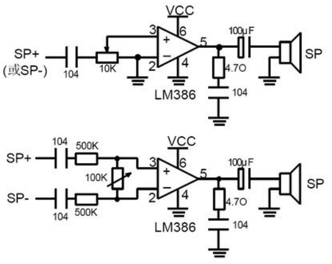
ADDING A POWER AMPLIFIER:
If you want an external power amplifier circuit to connect with speakers, you can use LM386, D2283, D2322, TA7368, MC34119, etc amplifier IC. Note, SP+ or SP‐ is you do not want to use, must vacant, do not connect to GND. Used LM386 power amplifier circuit as below: