L298P PWM Motor Drive Expansion Shield User’s Guide
User’s Guide
L298P PWM Motor Drive Expansion Shield
1. Product Overview
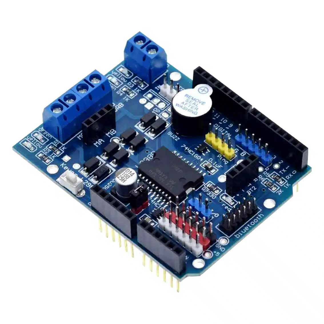
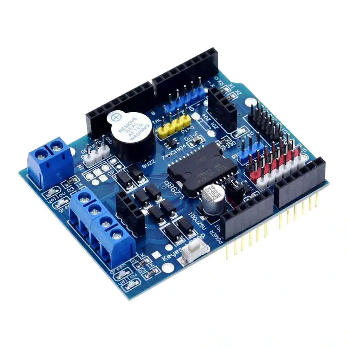
The L298P shield is an Arduino expansion board based on the L298 dual H‑bridge driver IC. It allows you to control two DC motors or one stepper motor, with support for PWM speed control and direction control directly from Arduino pins.
- Operating Voltage: 5V logic, motor supply 7–12V (up to 40V max with external supply)
- Current Capacity: ~2A per channel (peak)
- Motors Supported: 2 DC motors or 1 stepper motor
- Control Method: Arduino digital pins + PWM
2. Pinout & Connections
Typical L298P shield has:
| Pin/Terminal | Function |
|---|---|
| MA+, MA- | Motor A outputs |
| MB+, MB- | Motor B outputs |
| ENA | Enable/PWM for Motor A |
| ENB | Enable/PWM for Motor B |
| IN1, IN2 | Control inputs for Motor A direction |
| IN3, IN4 | Control inputs for Motor B direction |
| VIN | External motor supply (7–12V recommended) |
| 5V | Logic supply (from Arduino) |
| GND | Ground |
3. Control Logic
Each motor channel works as an H‑bridge:
| IN1 | IN2 | Motor A Action |
|---|---|---|
| HIGH | LOW | Forward |
| LOW | HIGH | Reverse |
| LOW | LOW | Stop (coast) |
| HIGH | HIGH | Brake |
- Same logic applies for Motor B using IN3/IN4.
- Apply PWM to ENA/ENB pins for speed control.
4. Wiring Guide (Arduino Example)
- Plug the shield directly onto Arduino UNO/Mega.
- Connect Motor A wires → MA+ / MA-.
- Connect Motor B wires → MB+ / MB-.
- Supply external motor voltage → VIN + GND terminals.
- Arduino provides logic signals automatically via shield pin mapping.
5. Example Arduino Code
int ENA = 9;   // PWM pin for Motor A
int IN1 = 8;
int IN2 = 7;

void setup() {
  pinMode(ENA, OUTPUT);
  pinMode(IN1, OUTPUT);
  pinMode(IN2, OUTPUT);
}

void loop() {
  // Forward at half speed
  digitalWrite(IN1, HIGH);
  digitalWrite(IN2, LOW);
  analogWrite(ENA, 128); // 50% duty cycle
  delay(2000);

  // Reverse at full speed
  digitalWrite(IN1, LOW);
  digitalWrite(IN2, HIGH);
  analogWrite(ENA, 255); // 100% duty cycle
  delay(2000);

  // Stop
  digitalWrite(IN1, LOW);
  digitalWrite(IN2, LOW);
  analogWrite(ENA, 0);
  delay(2000);
}
6. Applications
- Robotics: Drive two DC motors for wheels.
- Automation: Control pumps, fans, or actuators.
- Educational kits: Demonstrate PWM speed control and H‑bridge logic.
- Stepper motors: Drive bipolar stepper motors with IN1–IN4 sequencing.
7. Best Practices
- Use external motor supply (7–12V) for reliable operation.
- Do not exceed 2A per channel.
- Always connect grounds together (Arduino + motor supply).
- Add flyback diodes or capacitors if motors cause noise.
- Use PWM for smooth speed control.