L9110S H-Bridge Dual Motor Driver Module User’s Guide

User’s Guide
L9110S Dual H‑Bridge Motor Driver Module
1. Product Overview
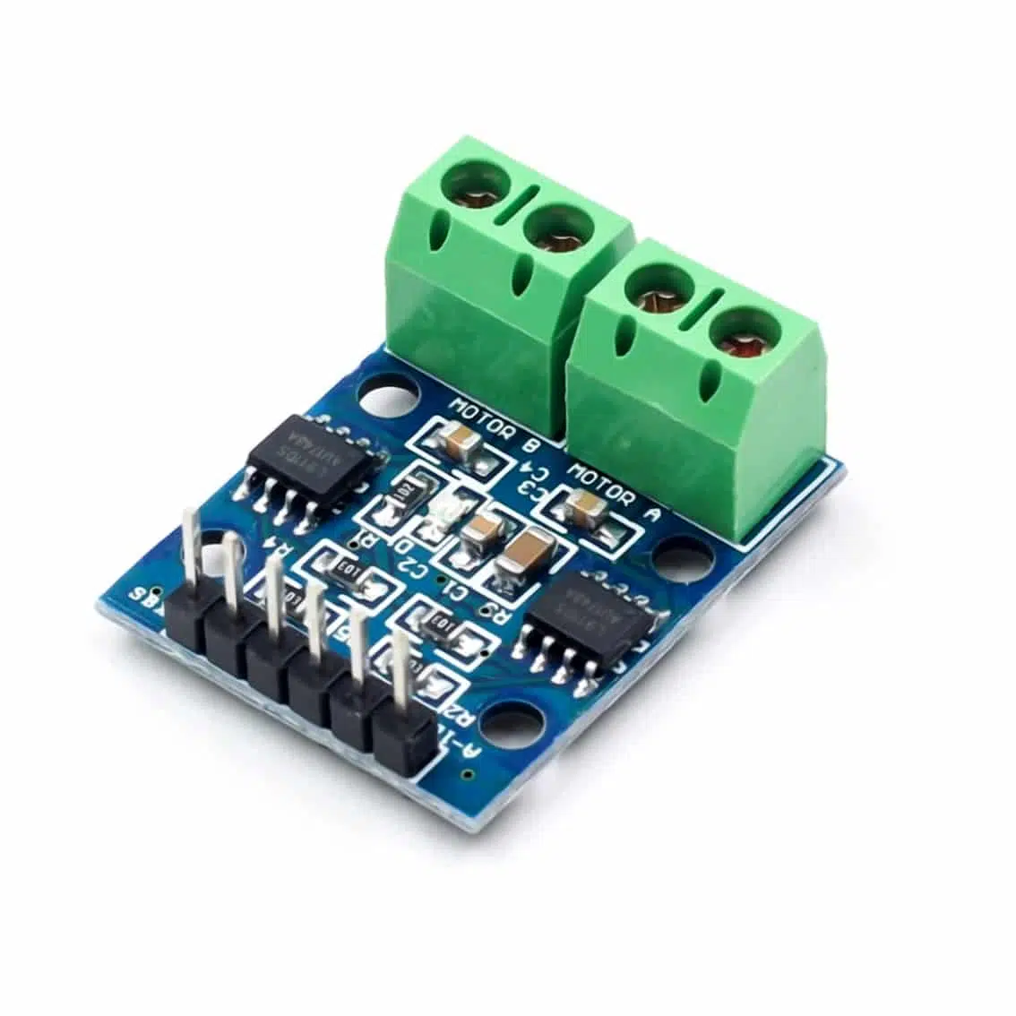
The L9110S is a compact dual‑channel motor driver IC mounted on a breakout board. It can control two DC motors or one small stepper motor, allowing forward/reverse motion and speed control via PWM signals.
- Operating Voltage: 2.5V – 12V DC
- Continuous Current: ~800mA per channel (peak up to ~1.5A)
- Control Method: Logic inputs (HIGH/LOW or PWM)
- Applications: Educational robots, toys, DIY kits, radio dial motors
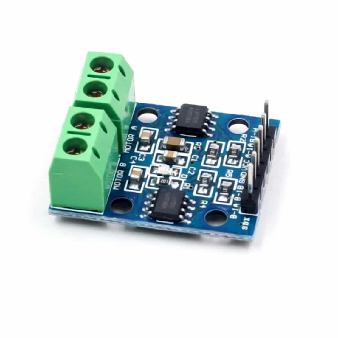
2. Pinout
Typical L9110S module has two channels (A & B):
| Pin | Function |
|---|---|
| VCC | Power supply (2.5–12V) |
| GND | Ground |
| A‑1A | Input 1 for Motor A |
| A‑1B | Input 2 for Motor A |
| B‑1A | Input 1 for Motor B |
| B‑1B | Input 2 for Motor B |
| Motor A | Output terminals for Motor A |
| Motor B | Output terminals for Motor B |
3. Control Logic
Each motor channel works as an H‑bridge:
| IN1 | IN2 | Motor Action |
|---|---|---|
| HIGH | LOW | Forward |
| LOW | HIGH | Reverse |
| LOW | LOW | Stop (coast) |
| HIGH | HIGH | Brake |
- Apply PWM on one input while holding the other LOW → speed control.
4. Wiring Guide (Arduino Example)
- Connect VCC → Arduino 5V (or external supply within 2.5–12V).
- Connect GND → Arduino GND.
- Connect A‑1A, A‑1B → Arduino digital pins (e.g., D8, D9).
- Connect Motor A terminals → DC motor.
- Repeat for Motor B if using two motors.
5. Example Arduino Code
int IN1 = 8;
int IN2 = 9;

void setup() {
  pinMode(IN1, OUTPUT);
  pinMode(IN2, OUTPUT);
}

void loop() {
  // Forward
  digitalWrite(IN1, HIGH);
  digitalWrite(IN2, LOW);
  delay(2000);

  // Reverse
  digitalWrite(IN1, LOW);
  digitalWrite(IN2, HIGH);
  delay(2000);

  // Stop
  digitalWrite(IN1, LOW);
  digitalWrite(IN2, LOW);
  delay(2000);
}
6. Applications
- Small robots: Drive two DC motors for wheels.
- Stepper motor control: Sequence inputs for 2‑phase stepper motors.
- Educational kits: Demonstrate H‑bridge logic and PWM speed control.
- DIY projects: Fan control, toy car motors, tuning knobs.
7. Best Practices
- Do not exceed 12V supply or 1.5A peak current.
- Use PWM from microcontroller for smooth speed control.
- Add flyback diodes if driving inductive loads beyond spec.
- Keep wiring short to reduce noise and voltage drop.