
← Back
You are here:
Print
Nano 3.0 ATmega328 Development Board with USB Cable – Arduino Compatible User’s Guide
Last Updated On
0
0
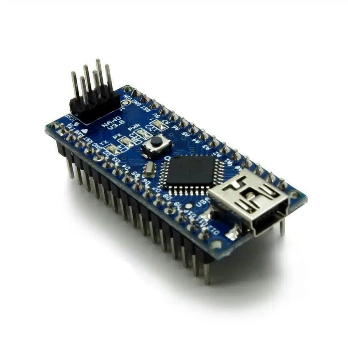
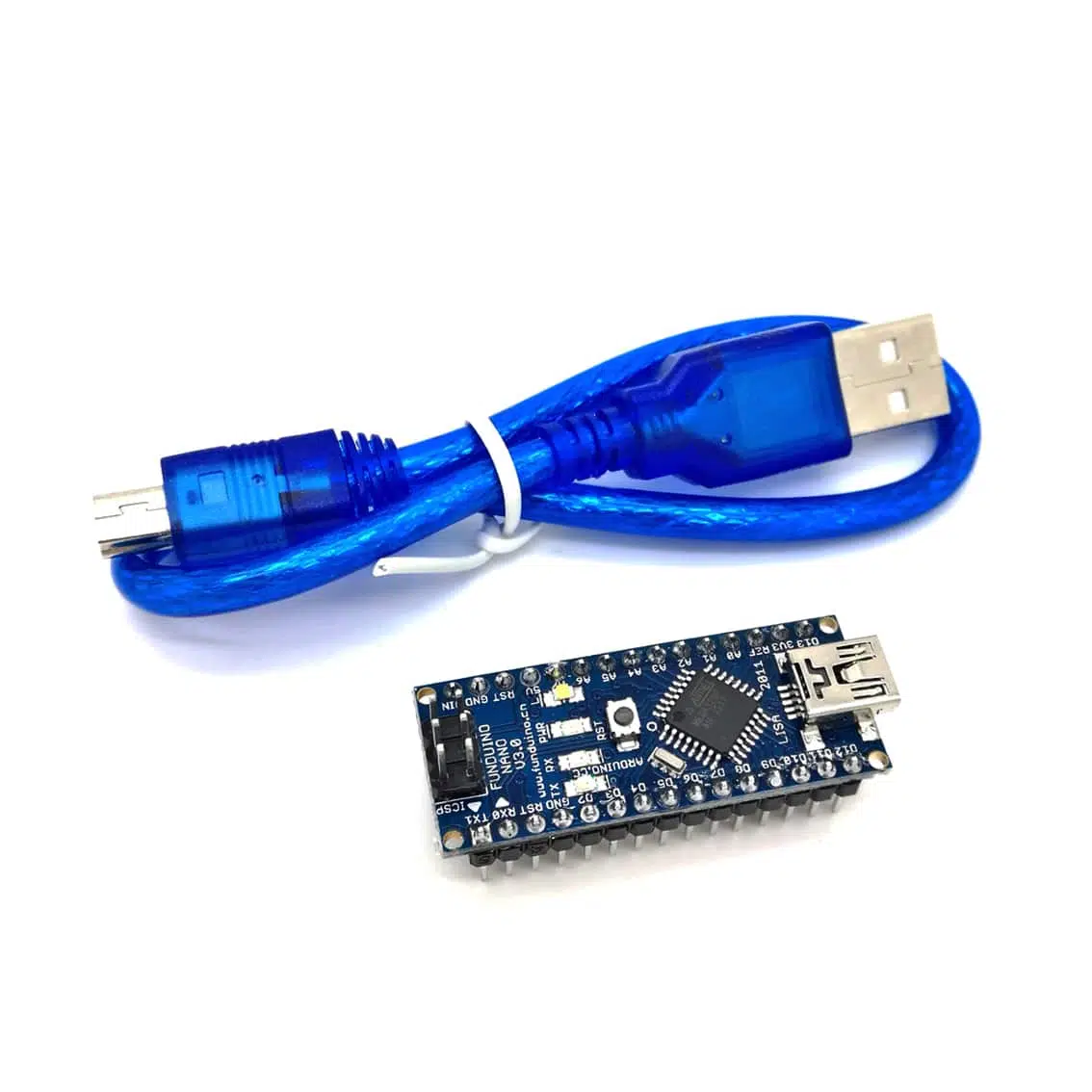
Product Overview
- Microcontroller: ATmega328P (16 MHz clock speed)
- Operating Voltage: 5 V
- Flash Memory: 32 KB (2 KB used by bootloader)
- SRAM: 2 KB
- EEPROM: 1 KB
- Digital I/O Pins: 22 (14 standard + 8 analog usable as digital)
- Analog Input Pins: 8 (A0–A7)
- PWM Outputs: 6 (D3, D5, D6, D9, D10, D11)
- USB Interface: Mini‑USB (for programming and power)
- Power Options:
- Via USB (5 V regulated)
- VIN pin (6–20 V unregulated)
- 5 V pin (regulated external supply)
Pinout Diagrams
Here is a clear pinout reference for your Nano 3.0 board:
- Detailed Nano v3.6 Pinout (TX/RX, I²C, SPI, PWM)
Setup Instructions
- Install Arduino IDE
- Download from Arduino.cc.
- Select Tools → Board → Arduino Nano.
- Choose Processor → ATmega328P (Old Bootloader) if uploads fail.
- Connect Board
- Use the included Mini‑USB cable.
- Install drivers if required (CH340 or FTDI depending on clone).
- Powering Options
- USB (default, 5 V regulated).
- VIN pin for external supply (7–12 V recommended).
- 5 V pin for regulated external supply.
Example Code
Blink onboard LED (D13):
cpp
void setup() {
  pinMode(13, OUTPUT);
}

void loop() {
  digitalWrite(13, HIGH);
  delay(1000);
  digitalWrite(13, LOW);
  delay(1000);
}
Upload via Arduino IDE → Upload button.
Key Pin Functions
| Pin | Function | Notes |
|---|---|---|
| D0/D1 | RX/TX | Serial communication |
| D2/D3 | External interrupts | attachInterrupt() |
| D3, D5, D6, D9, D10, D11 | PWM outputs | analogWrite() |
| D10–D13 | SPI | SS, MOSI, MISO, SCK |
| A4/A5 | I²C | SDA, SCL |
| A0–A7 | Analog inputs | 10‑bit ADC |
| VIN | External power | 7–12 V recommended |
| 5V | Regulated output | From USB or regulator |
| 3V3 | 3.3 V output | Limited current |
| RESET | Reset board | Manual reset |
Risks & Best Practices
- Voltage caution: Operates at 5 V logic; avoid direct 12 V on GPIOs.
- Current limit: Max 40 mA per I/O pin.
- Bootloader issues: Some clones require “Old Bootloader” setting.
- Breadboard use: Nano is breadboard‑friendly but ensure firm connections.
Applications
- Robotics (motor control via PWM)
- IoT sensors (I²C/SPI communication)
- Educational kits for beginners
- Environmental monitoring projects
- Prototyping with breadboard circuits
Table of Contents