
NE555 Adjustable Pulse Frequency & Duty Cycle Module User’s Guide
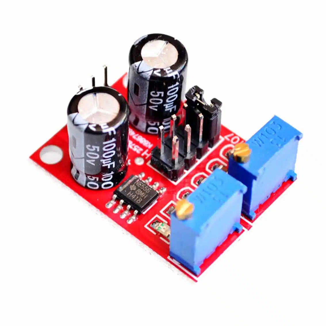
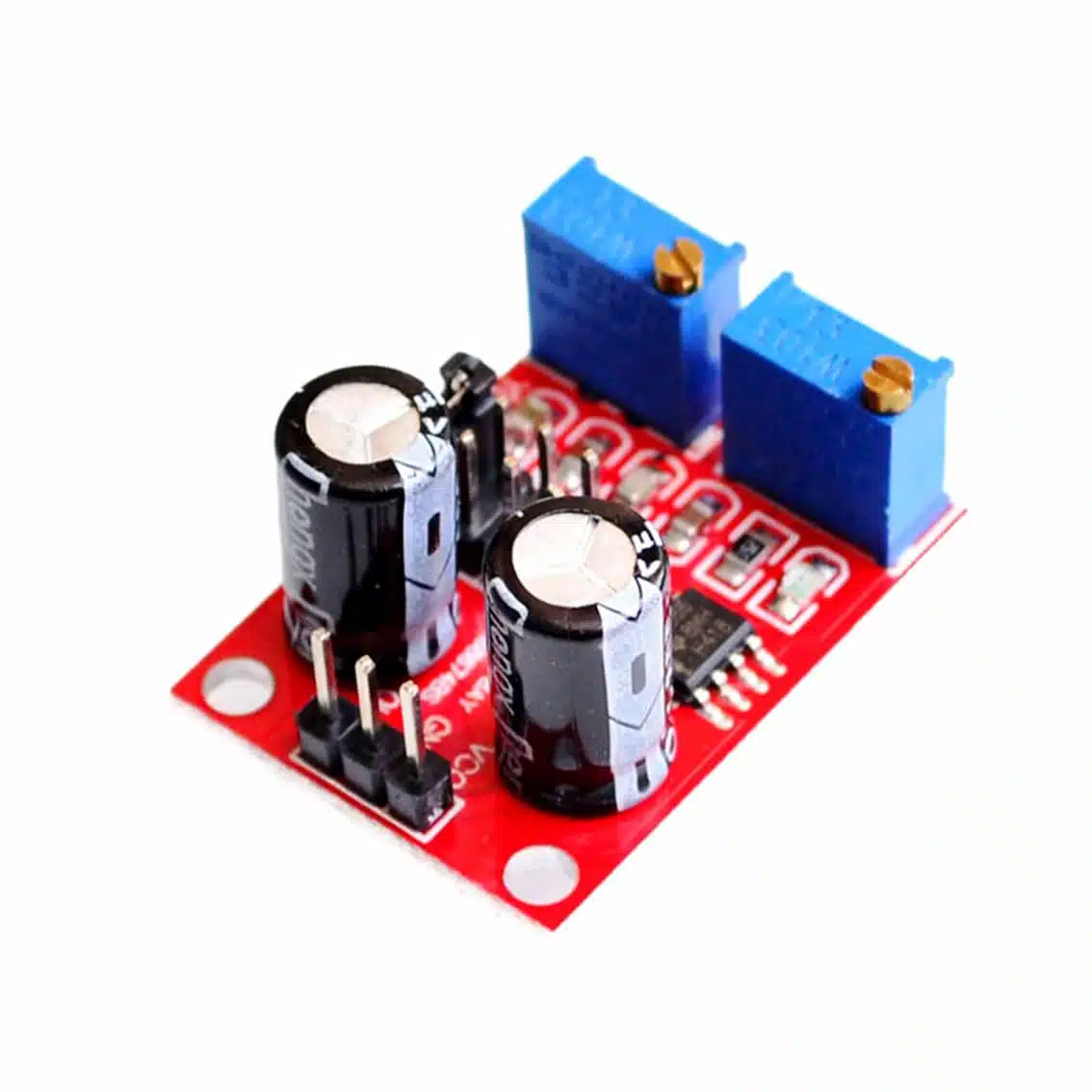
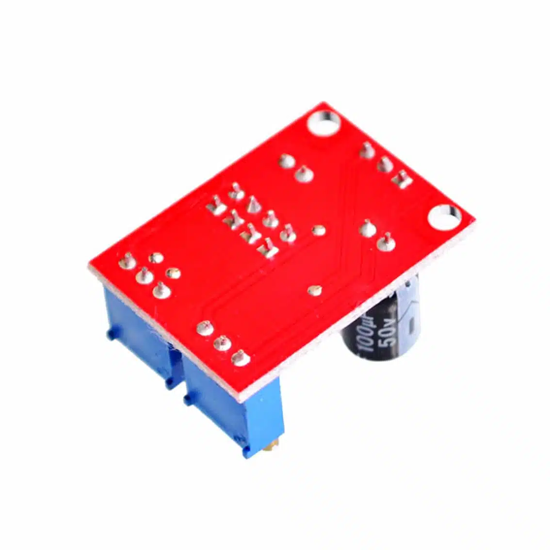
Module
1. Overview
- Based on the NE555 timer IC, configured in astable mode (continuous oscillation).
- Generates a square wave signal with adjustable frequency and duty cycle.
- Useful for:
- LED blinkers
- Tone generation
- PWM motor control
- Clock pulses for digital circuits
2. Specifications
- Supply Voltage: 5V – 15V
- Output Signal: Square wave
- Frequency Range: ~1Hz to 200kHz (range varied through headers)
- Duty Cycle: Adjustable (typically 5% – 95%)
- Pins:
- VCC → Power input
- GND → Ground
- OUT → Signal output
3. Pin Connections
| Pin | Function | Connect To |
|---|---|---|
| VCC | Power supply | 5V (Arduino) or external 3.3–12V |
| GND | Ground | Common ground |
| OUT | Output signal | LED, buzzer, motor driver, or microcontroller input |
4. Controls
- Potentiometer 1 (Frequency): Adjusts how fast pulses repeat.
- Potentiometer 2 (Duty Cycle): Adjusts HIGH vs LOW ratio of each cycle.
- Together, they let you set:
- Slow blinking LED (low frequency, ~50% duty cycle)
- Fast PWM for motor speed control (high frequency, variable duty cycle)
5. Example Projects
A. LED Blinker
- Connect OUT → LED (with resistor) → GND.
- Adjust frequency knob → LED blinks faster/slower.
- Adjust duty cycle knob → LED stays ON longer or shorter.
B. Tone Generator
- Connect OUT → small speaker (via transistor).
- Adjust frequency → pitch changes.
- Adjust duty cycle → tone quality changes.
C. PWM Motor Control
- Connect OUT → transistor/MOSFET → DC motor.
- Adjust duty cycle → motor speed changes.
- Keep frequency high (~20kHz) to avoid audible noise.
6. Best Practices
- Use a stable power supply for consistent output.
- Don’t drive motors directly from the OUT pin — use a transistor or driver.
- For precise tuning, measure output with an oscilloscope or frequency counter.
- Keep duty cycle within safe ranges for motors (20–80%).
7. Quick Demo Setup
VCC → 5V (Arduino or USB supply)
GND → Arduino GND
OUT → LED + 220Ω resistor → GND
- Turn knobs → watch LED blink speed and brightness change.