
NE555 Frequency Adjustable Pulse Generator Module – User’s Guide
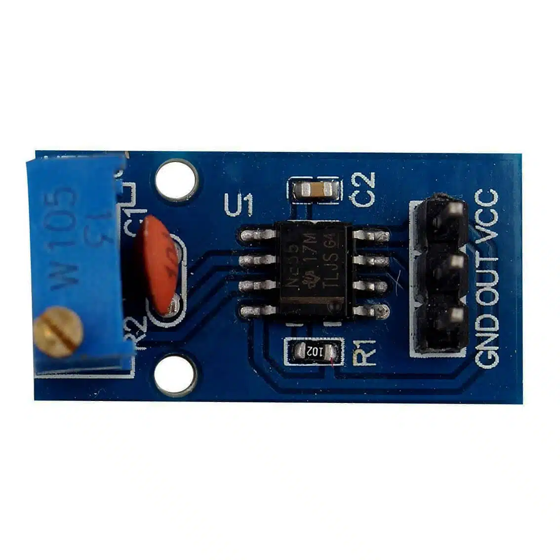
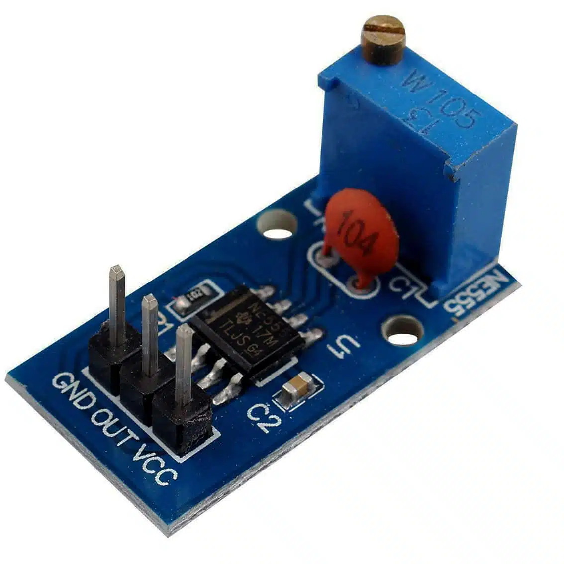
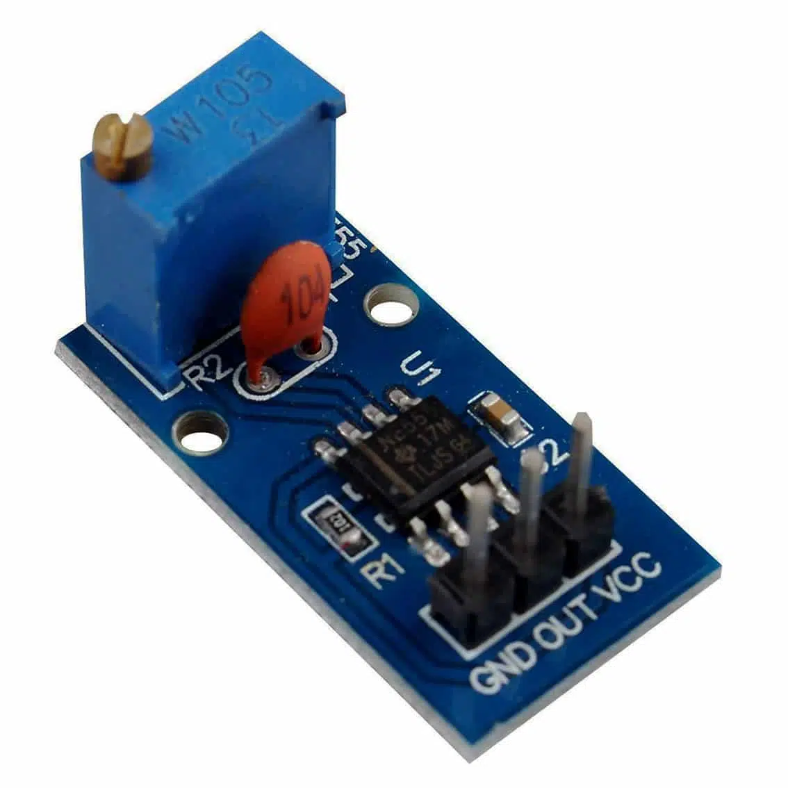
1. Overview
This module uses the NE555 timer IC in astable mode to generate square wave pulses. It’s simple, reliable, and ideal for educational kits, PWM experiments, LED blinkers, and signal testing.
2. Specifications (based on your module)
- Operating Voltage: 5–12 V DC
- Frequency Range:
- Minimum: 3.7 Hz (≈ 0.27 s period)
- Maximum: 1.3 kHz (≈ 770 µs period)
- Duty Cycle Range: 50% (minimum) to 98% (maximum)
- Current Consumption: >100 mA
- Maximum Output Current:
- 15 mA at 5 V input
- 30 mA at 12 V input
- Core IC: NE555 timer
- Output Signal: Square wave (digital pulses)
3. Pinout & Terminals
| Pin | Function |
|---|---|
| VCC | Power supply (5–12 V DC) |
| GND | Ground |
| OUT | Square wave output |
4. Controls
- Potentiometer (Frequency):
- Clockwise → higher frequency (shorter period, faster pulses).
- Counterclockwise → lower frequency (longer period, slower pulses).
- Duty cycle is automatically linked to frequency (not independently adjustable).
5. Example Wiring
Basic Setup
- VCC → 5V (Arduino or external supply)
- GND → Common ground
- OUT → Arduino digital pin (e.g., D2)
6. Example Arduino Integration
int pulsePin = 2;

void setup() {
  pinMode(pulsePin, INPUT);
  Serial.begin(9600);
}

void loop() {
  int val = digitalRead(pulsePin);
  Serial.println(val); // Reads HIGH/LOW pulses
}
This lets you monitor the pulses or use them as a clock source for counters, shift registers, or other digital circuits.
7. Applications
- LED flasher (adjustable blink rate)
- Tone generator (feed into a speaker)
- PWM-like source (motor speed control via transistor/MOSFET)
- Clock pulses for digital ICs (counters, shift registers)
- Signal injection for testing circuits
8. Best Practices
- Use a stable DC supply for consistent output.
- Don’t overload the OUT pin — max 15 mA at 5 V, 30 mA at 12 V.
- For driving motors or high-current loads, use the output to control a transistor or MOSFET.
- Add a decoupling capacitor (100 µF) across VCC/GND for stability.
- Use an oscilloscope or frequency counter to fine-tune settings.