NodeMCU ESP‑12E + Motor Shield Expansion Kit User’s Guide
User’s Guide
NodeMCU ESP‑12E + Motor Shield Expansion Kit
1. Product Overview
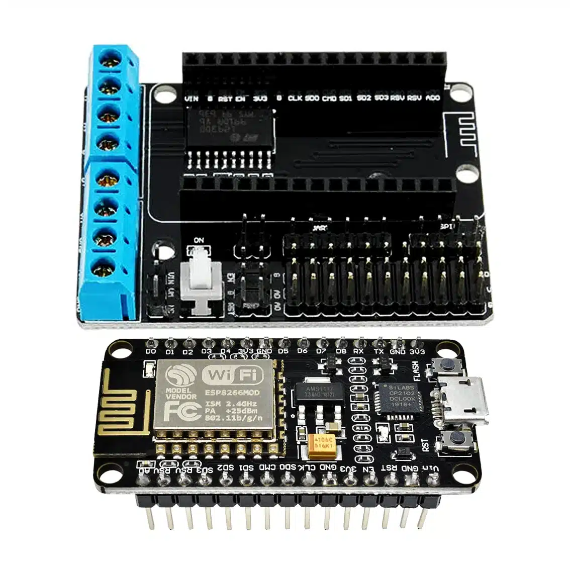
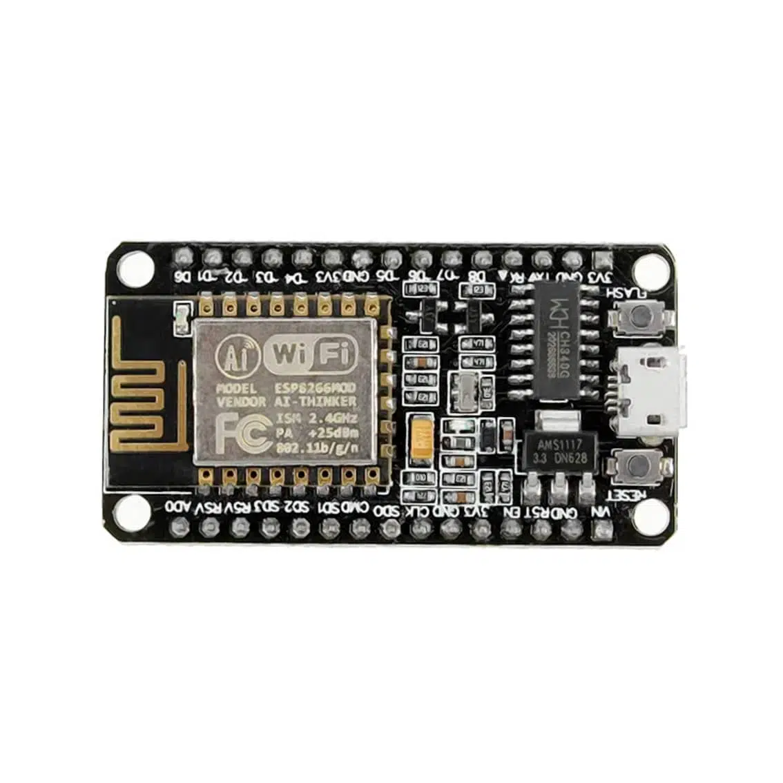
This kit combines the NodeMCU ESP‑12E (ESP8266 Wi‑Fi microcontroller) with a motor shield expansion board. Together, they allow you to control DC motors or a stepper motor directly from the ESP‑12E, while also enabling IoT features like Wi‑Fi remote control.
- Microcontroller: ESP8266 (NodeMCU ESP‑12E)
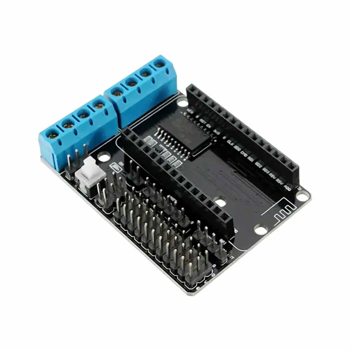
- Motor Driver IC: L293D (dual H‑bridge)
- Motors Supported: 2 DC motors or 1 stepper motor
- Control Method: GPIO pins + PWM signals from ESP8266
- Expansion Features: Screw terminals, pin headers, buzzer, Bluetooth/relay shield compatibility
2. Pinout & Connections
Motor Shield Terminals
| Terminal | Function |
|---|---|
| MA+, MA- | Motor A outputs |
| MB+, MB- | Motor B outputs |
| VIN | External motor supply (7–12V recommended) |
| GND | Ground |
| ENA | Enable/PWM for Motor A |
| ENB | Enable/PWM for Motor B |
| IN1, IN2 | Motor A direction control |
| IN3, IN4 | Motor B direction control |
NodeMCU ESP‑12E Pins (common mapping)
| Pin | Function |
|---|---|
| D1–D4 | Motor control inputs (mapped to IN1–IN4) |
| D5/D6 | PWM enable pins (ENA/ENB) |
| 3V3 | Logic supply |
| GND | Ground |
| VIN | External supply (USB or 7–12V via shield) |
3. Control Logic
Each motor channel works as an H‑bridge:
| IN1 | IN2 | Motor A Action |
|---|---|---|
| HIGH | LOW | Forward |
| LOW | HIGH | Reverse |
| LOW | LOW | Stop (coast) |
| HIGH | HIGH | Brake |
- Same logic applies for Motor B using IN3/IN4.
- Apply PWM to ENA/ENB pins for speed control.
4. Wiring Guide
- Plug the motor shield onto the NodeMCU ESP‑12E.
- Connect Motor A wires → MA+ / MA-.
- Connect Motor B wires → MB+ / MB-.
- Supply external motor voltage → VIN + GND terminals.
- Power NodeMCU via USB (for programming) or external VIN.
5. Example Arduino Code (ESP8266)
int IN1 = D1;
int IN2 = D2;
int ENA = D5;

void setup() {
  pinMode(IN1, OUTPUT);
  pinMode(IN2, OUTPUT);
  pinMode(ENA, OUTPUT);
}

void loop() {
  // Forward at half speed
  digitalWrite(IN1, HIGH);
  digitalWrite(IN2, LOW);
  analogWrite(ENA, 512); // 50% duty cycle
  delay(2000);

  // Reverse at full speed
  digitalWrite(IN1, LOW);
  digitalWrite(IN2, HIGH);
  analogWrite(ENA, 1023); // 100% duty cycle
  delay(2000);

  // Stop
  digitalWrite(IN1, LOW);
  digitalWrite(IN2, LOW);
  analogWrite(ENA, 0);
  delay(2000);
}
6. Applications
- Wi‑Fi controlled robots: Drive two DC motors for wheels.
- IoT automation: Control fans, pumps, or actuators via Wi‑Fi.
- Educational kits: Demonstrate PWM speed control and H‑bridge logic.
- Stepper motor projects: Drive bipolar stepper motors with IN1–IN4 sequencing.
7. Best Practices
- Use external motor supply (7–12V) for reliable operation.
- Do not exceed 600mA per channel (L293D limit).
- Always connect grounds together (ESP8266 + motor supply).
- Add flyback diodes or capacitors if motors cause noise.
- Use PWM for smooth speed control.