
PCA9685 16‑Channel 12‑bit PWM Servo Driver – User’s Guide
PCA9685 16‑Channel 12‑bit PWM Servo Driver – User’s Guide
1. Overview
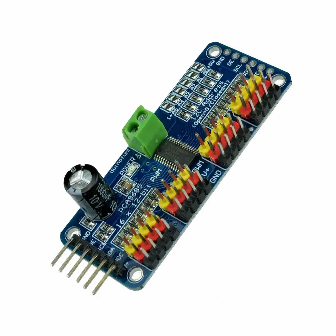
The PCA9685 is an I²C‑controlled PWM driver with 16 independent channels. It’s widely used to control servo motors, LEDs, and other PWM‑driven devices. Each channel has 12‑bit resolution (4096 steps), allowing precise duty cycle control.
2. Specifications
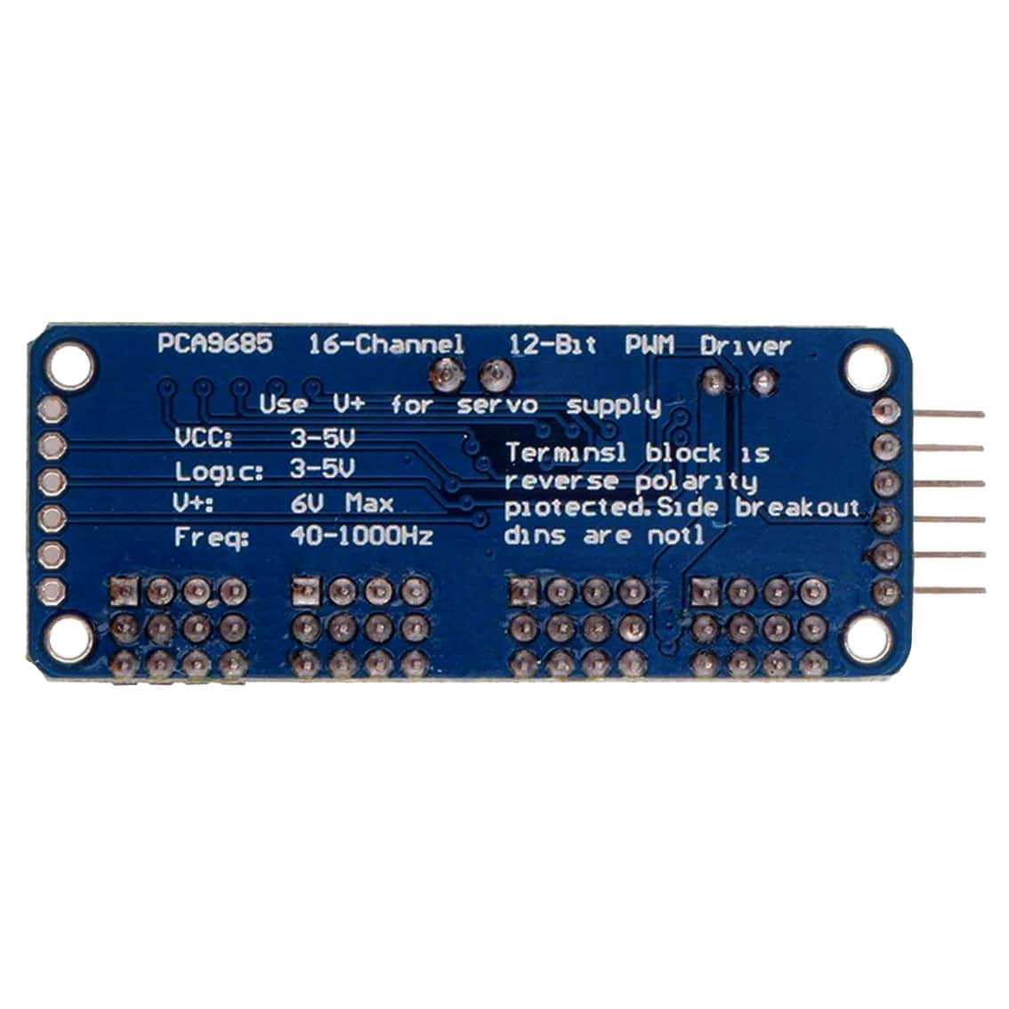
- Logic Voltage (VCC): 3.0–5.0 V
- Servo Supply (V+): up to 6 V max
- PWM Frequency: 40–1000 Hz (default ~50–60 Hz for servos)
- Channels: 16 (independent, 12‑bit resolution)
- Interface: I²C bus (address configurable via jumpers A0–A5)
- Protection: Terminal block is reverse‑polarity protected (side pin headers are not)
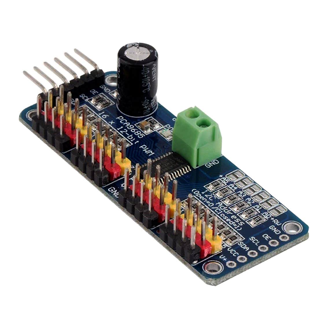
3. Pinout & Terminals (based on your boards)
Power & Logic
| Pin | Function |
|---|---|
| VCC | Logic supply (3–5 V) |
| GND | Ground |
| V+ | External servo/LED power (≤6 V) |
I²C Interface
| Pin | Function |
|---|---|
| SCL | I²C clock line |
| SDA | I²C data line |
| OE | Output enable (active LOW, can disable all PWM outputs) |
Address Selection
- A0–A5 jumpers: Configure I²C address (open = 0, closed = 1).
- Base address:
0x40(can be changed up to0x7Fusing jumpers).
Outputs
- PWM0–PWM15: 16 channels for servos/LEDs.
- Each channel has 3 pins: GND, V+, Signal (on side headers or terminal block).
4. Wiring Example
Controller → PCA9685
- VCC → 3.3 V or 5 V (depending on MCU)
- GND → Common ground
- SCL → Arduino/ESP32 SCL pin
- SDA → Arduino/ESP32 SDA pin
Servo Power
- V+ → External 5–6 V supply
- GND → Common ground with MCU
Servo Motor
- Connect servo’s signal wire → PWM channel pin
- Servo’s power wire → V+
- Servo’s ground wire → GND
5. Example Arduino Code (using Adafruit PCA9685 library)
#include <Wire.h>
#include <Adafruit_PWMServoDriver.h>

Adafruit_PWMServoDriver pwm = Adafruit_PWMServoDriver();

void setup() {
  pwm.begin();
  pwm.setPWMFreq(60); // 60 Hz for servos
}

void loop() {
  // Example: sweep servo on channel 0
  for (int pulse = 150; pulse < 600; pulse++) {
    pwm.setPWM(0, 0, pulse);
    delay(10);
  }
  for (int pulse = 600; pulse > 150; pulse--) {
    pwm.setPWM(0, 0, pulse);
    delay(10);
  }
}
6. Applications
- Robotics (multi‑servo control)
- CNC machines & automation
- LED dimming arrays
- Animatronics & educational kits
7. Best Practices
- Always use a separate power supply for servos (V+), not from the MCU.
- Tie grounds together (MCU GND ↔ PCA9685 GND ↔ Servo GND).
- Keep servo supply ≤6 V to avoid damage.
- Use decoupling capacitors (e.g., 1000 µF across V+/GND) for stable servo power.
- Configure I²C address jumpers if using multiple PCA9685 boards.