
TB6560 3A Single‑Axis Stepper Motor Driver Board User’s Guide
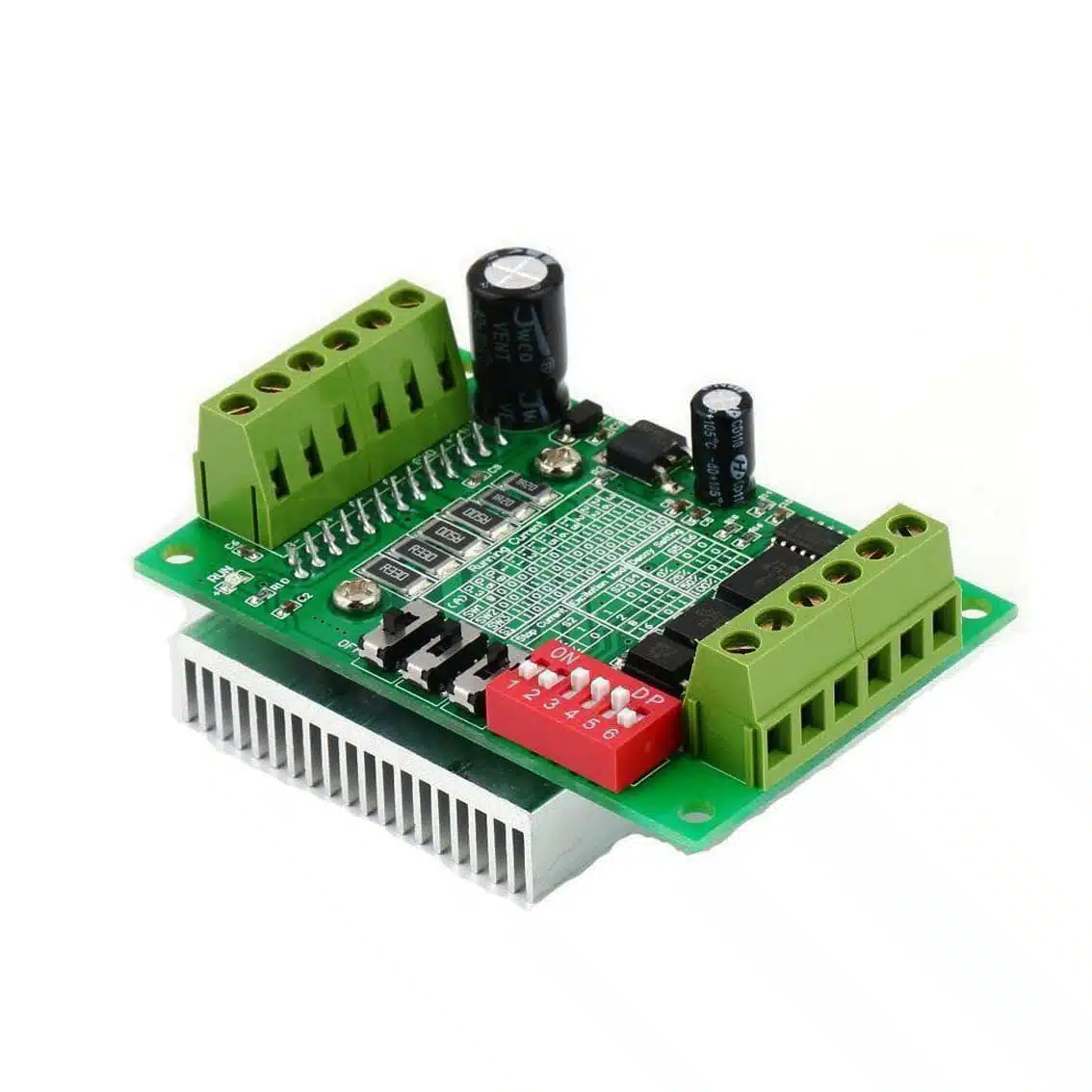
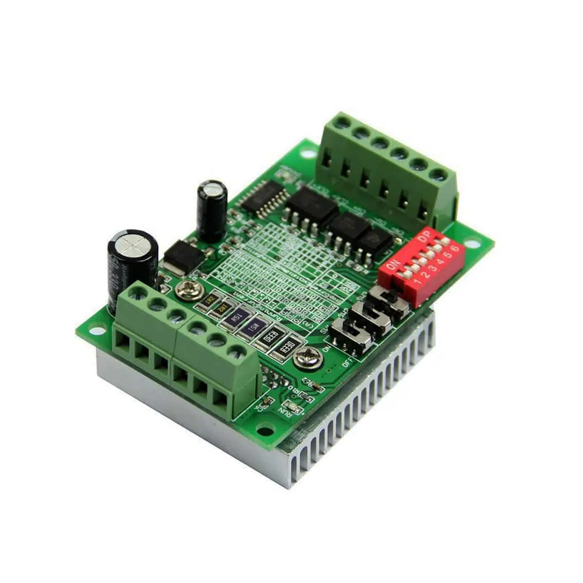
1. Overview
The TB6560 driver board controls 2‑phase bipolar stepper motors with up to 3A per phase. It supports microstepping, current limiting, and direction control, making it ideal for CNC machines, robotics, and educational kits.
2. Specifications
- Input Voltage: 10–35V DC (recommended 12–24V)
- Max Output Current: 3A per phase
- Supported Motors: 2‑phase bipolar stepper motors (NEMA 17, NEMA 23, etc.)
- Microstepping: Up to 1/64 step (configurable via DIP switches)
- Control Signals: Step (CLK), Direction (CW), Enable (ENA)
3. Pinout (Detailed)
Power Terminals
| Pin | Function | Notes |
|---|---|---|
| VCC | Motor power supply (10–35V DC) | Use regulated DC supply |
| GND | Ground | Must be common with controller ground |
Motor Terminals
| Pin | Function | Notes |
|---|---|---|
| A+ / A- | Motor coil A | Connect one coil pair |
| B+ / B- | Motor coil B | Connect second coil pair |
Identify coil pairs with a multimeter (two wires with continuity = one coil).
Control Signal Terminals
| Pin | Meaning | Function |
|---|---|---|
| CLK+ / CLK‑ | Clock (Step) signal | Each pulse = one step/microstep. Connect to controller STEP output. |
| CW+ / CW‑ | Direction signal | Sets motor rotation direction (clockwise/counter‑clockwise). Connect to controller DIR output. |
| ENA+ / ENA‑ | Enable signal | Turns driver on/off. Connect to controller ENABLE output. |
4. DIP Switch Settings
- SW1–SW3: Current limit (set to motor’s rated current, up to 3A).
- SW4–SW6: Microstepping resolution (Full, 1/2, 1/8, 1/16, 1/32, 1/64).
- Other small switches (SW1–SW3 on board edge): Often configure decay mode or idle current.
Always check the silkscreen table printed on your board for exact switch positions.
5. Example Wiring (Arduino UNO)
Arduino 5V  → CLK+, CW+, ENA+
Arduino GND → CLK-, CW-, ENA-
D2 → CLK+ (Step)
D3 → CW+ (Direction)
D4 → ENA+ (Enable)
Motor coils → A+, A- and B+, B-
12–24V DC → VCC / GND
6. Example Code (Arduino)
int stepPin = 2;
int dirPin = 3;
int enaPin = 4;

void setup() {
  pinMode(stepPin, OUTPUT);
  pinMode(dirPin, OUTPUT);
  pinMode(enaPin, OUTPUT);
  digitalWrite(enaPin, LOW); // Enable driver
}

void loop() {
  digitalWrite(dirPin, HIGH); // Set direction
  for(int x=0; x<200; x++) {  // 200 steps = 1 revolution (depends on microstep setting)
    digitalWrite(stepPin, HIGH);
    delayMicroseconds(500);
    digitalWrite(stepPin, LOW);
    delayMicroseconds(500);
  }
  delay(1000);
}
7. Applications
- CNC machines (X, Y, Z axis control)
- Robotics (precise positioning)
- 3D printers (stepper motor control)
- Educational kits for motor driver learning
8. Best Practices
- Use a dedicated power supply (12–24V DC recommended).
- Match current limit to your motor’s rated current.
- Always connect controller ground to driver ground.
- Ensure proper cooling — keep the heat sink unobstructed.
- Avoid rapid direction changes without short delays.