TB6600 Stepper Motor Driver – User’s Guide
1. Overview
The TB6600 is a robust stepper motor driver for 2-phase bipolar stepper motors. It supports adjustable current, microstepping, and has built-in protection features. Commonly used in CNC machines, 3D printers, and robotics, it allows precise control of motor movement.
2. Specifications
- Input Voltage: 9–42 V DC
- Output Current: 0.5–4.5 A (set via DIP switches)
- Microstepping: Full step to 1/64 step
- Control Signals: Pulse (PUL), Direction (DIR), Enable (ENA)
- Protection: Over-voltage, over-current, thermal shutdown
- Motor Compatibility: Bipolar stepper motors (NEMA 17, 23, 34)
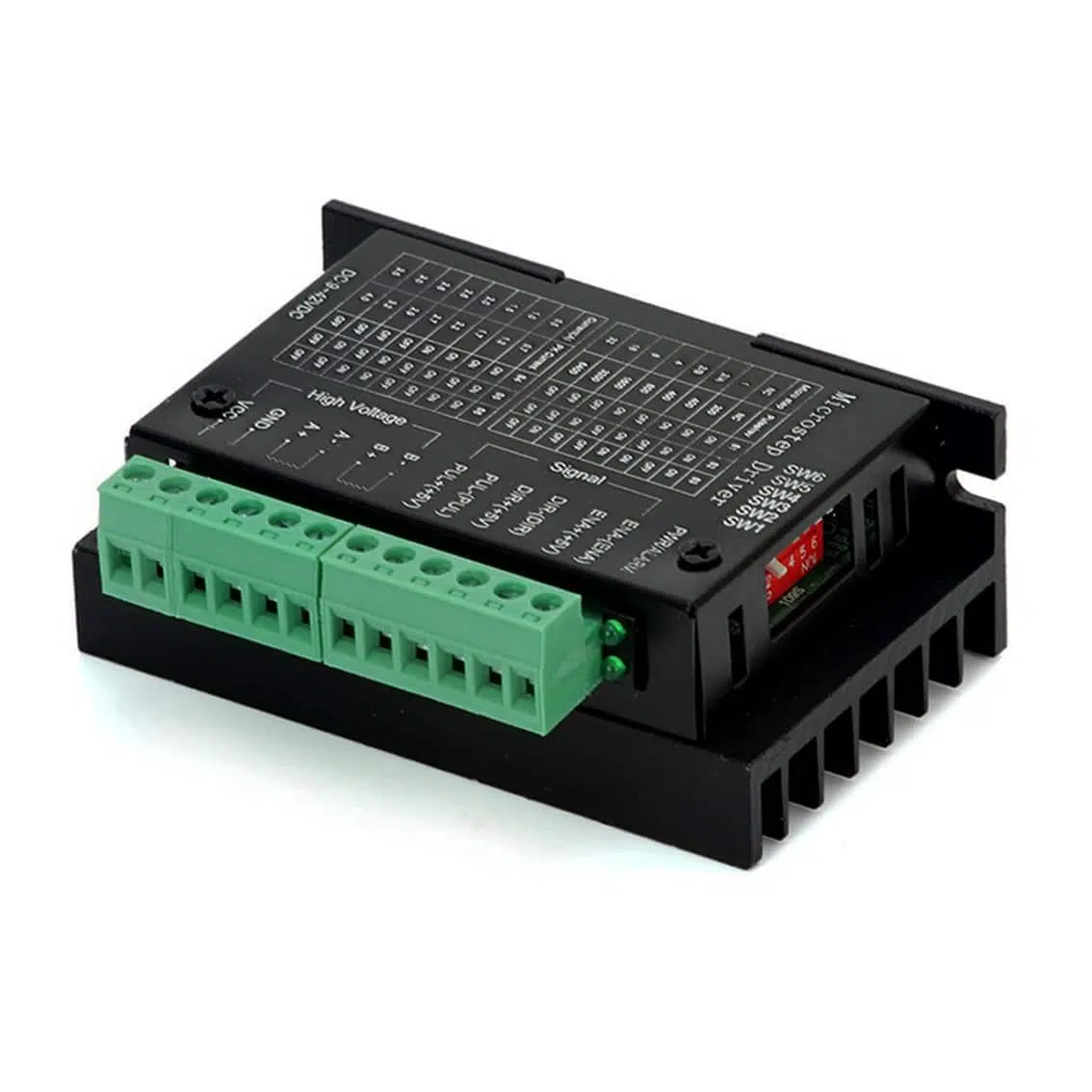
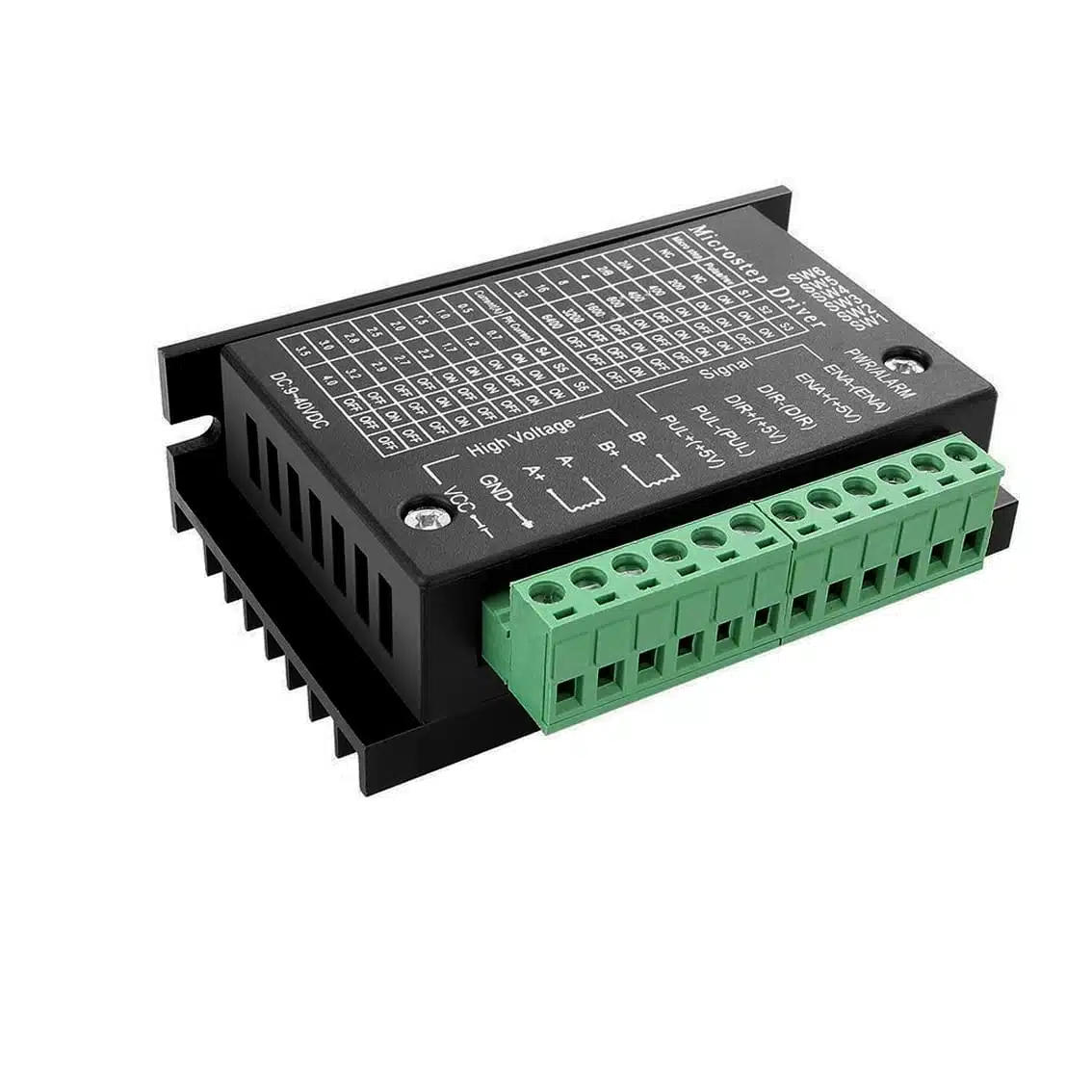
3. Terminal Connections
Signal Inputs
| Terminal | Function |
|---|---|
| PUL+ / PUL- | Step pulse input |
| DIR+ / DIR- | Direction control |
| ENA+ / ENA- | Enable signal |
Power & Motor Outputs
| Terminal | Function |
|---|---|
| VCC / GND | DC power supply (9–42 V) |
| A+ / A- | Motor coil A |
| B+ / B- | Motor coil B |
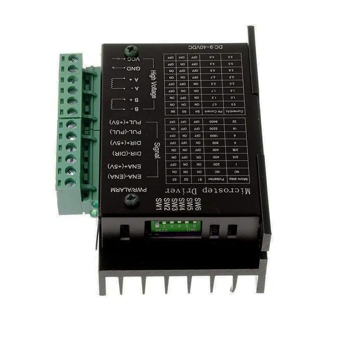
4. DIP Switch Settings (from enlarged casing tables)
Current Settings
| SW1 | SW2 | SW3 | Current (A) |
|---|---|---|---|
| OFF | OFF | OFF | 0.5 |
| ON | OFF | OFF | 1.0 |
| OFF | ON | OFF | 1.5 |
| ON | ON | OFF | 2.0 |
| OFF | OFF | ON | 2.5 |
| ON | OFF | ON | 3.0 |
| OFF | ON | ON | 3.5 |
| ON | ON | ON | 4.5 |
Microstep Resolution
| SW4 | SW5 | SW6 | Steps per Revolution |
|---|---|---|---|
| OFF | OFF | OFF | 200 (Full step) |
| ON | OFF | OFF | 400 (1/2 step) |
| OFF | ON | OFF | 800 (1/4 step) |
| ON | ON | OFF | 1600 (1/8 step) |
| OFF | OFF | ON | 3200 (1/16 step) |
| ON | OFF | ON | 6400 (1/32 step) |
| OFF | ON | ON | 12800 (1/64 step) |
5. Wiring Example
Controller → TB6600
- PUL+ → 5V
- PUL- → Arduino/ESP32 pin (e.g., D2)
- DIR+ → 5V
- DIR- → Arduino/ESP32 pin (e.g., D3)
- ENA+ → 5V
- ENA- → Arduino/ESP32 pin (optional, e.g., D4)
Motor → TB6600
- A+ / A- → Coil A
- B+ / B- → Coil B
Power Supply
- VCC → 24 V DC (recommended)
- GND → Power ground
6. Example Arduino Code
#define PUL 2
#define DIR 3
#define ENA 4

void setup() {
  pinMode(PUL, OUTPUT);
  pinMode(DIR, OUTPUT);
  pinMode(ENA, OUTPUT);
  digitalWrite(ENA, LOW); // Enable driver
}

void loop() {
  digitalWrite(DIR, HIGH); // Set direction
  for (int i = 0; i < 200; i++) { // 200 steps = 1 revolution (full step)
    digitalWrite(PUL, HIGH);
    delayMicroseconds(500);
    digitalWrite(PUL, LOW);
    delayMicroseconds(500);
  }
  delay(1000);
}
7. Applications
- CNC routers & mills
- Laser engravers
- 3D printers
- Robotics (linear/rotary motion)
- Automated machinery
8. Best Practices
- Use a stable DC supply (24 V recommended).
- Match current setting to motor’s rated current.
- Provide cooling (heatsink/fan).
- Use shielded cables for long signal wires.
- Double-check coil wiring (A+/A-, B+/B-).