TB6612FNG Dual Motor Driver Module User’s Guide
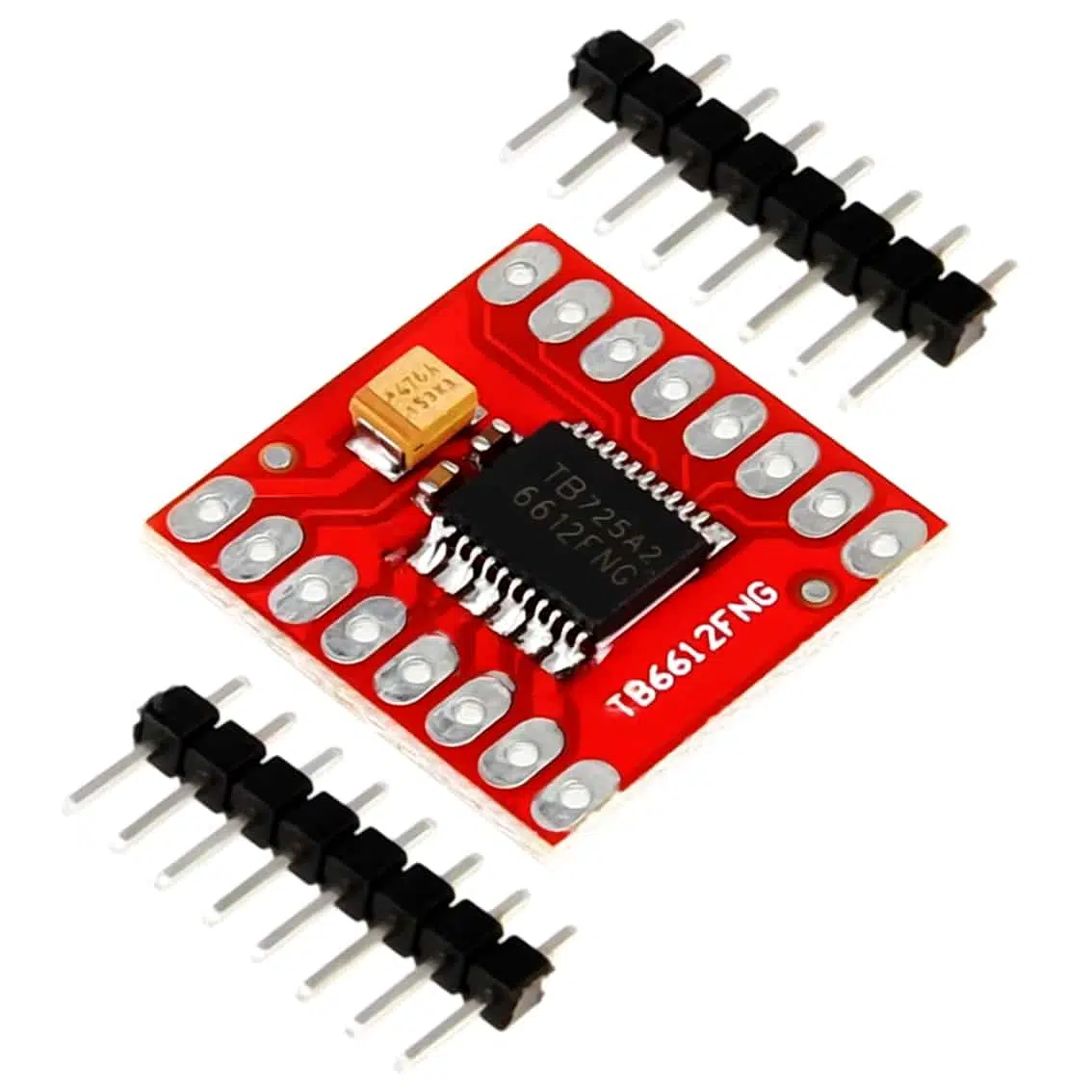
1. Overview
- Driver IC: TB6612FNG (dual H‑bridge).
- Motors Supported:
- 2 DC motors (independent control).
- 1 bipolar stepper motor (using both channels).
- Voltage Range:
- Logic: 2.7–5.5 V (works with Arduino, ESP8266, ESP32, Raspberry Pi).
- Motor: 4.5–13.5 V.
- Current Capacity: ~1.2 A continuous per channel, 3.2 A peak.
- Efficiency: Lower heat, higher efficiency than L293D/L298N.
- Protection: Built‑in diodes for back‑EMF.
2. Pinout
Typical breakout board pins:
| Pin | Function | Description |
|---|---|---|
| VCC | Logic supply (2.7–5.5 V) | |
| VM | Motor supply (4.5–13.5 V) | |
| GND | Ground | |
| PWMA | PWM input for Motor A | |
| AIN1, AIN2 | Direction inputs for Motor A | |
| PWMB | PWM input for Motor B | |
| BIN1, BIN2 | Direction inputs for Motor B | |
| STBY | Standby (LOW = sleep, HIGH = active) | |
| AO1, AO2 | Motor A outputs | |
| BO1, BO2 | Motor B outputs |
3. How It Works
- Each motor channel is an H‑bridge.
- AIN1/AIN2 + PWMA control Motor A.
- BIN1/BIN2 + PWMB control Motor B.
- STBY must be HIGH to enable the driver.
- By toggling IN pins and applying PWM, you can set forward, reverse, brake, or stop.
4. Wiring Example (Arduino UNO, 2 DC Motors)
TB6612FNG Pin → Arduino Pin
AIN1 → D2
AIN2 → D3
PWMA → D5 (PWM)
BIN1 → D4
BIN2 → D7
PWMB → D6 (PWM)
STBY → D8
VCC → 5V
VM → External motor supply (e.g., 9V battery)
GND → GND
5. Arduino Code Example
int AIN1 = 2;
int AIN2 = 3;
int PWMA = 5;
int BIN1 = 4;
int BIN2 = 7;
int PWMB = 6;
int STBY = 8;

void setup() {
  pinMode(AIN1, OUTPUT);
  pinMode(AIN2, OUTPUT);
  pinMode(PWMA, OUTPUT);
  pinMode(BIN1, OUTPUT);
  pinMode(BIN2, OUTPUT);
  pinMode(PWMB, OUTPUT);
  pinMode(STBY, OUTPUT);
  digitalWrite(STBY, HIGH); // enable driver
}

void loop() {
  // Motor A forward
  digitalWrite(AIN1, HIGH);
  digitalWrite(AIN2, LOW);
  analogWrite(PWMA, 200); // speed 200/255

  // Motor B reverse
  digitalWrite(BIN1, LOW);
  digitalWrite(BIN2, HIGH);
  analogWrite(PWMB, 150); // speed 150/255

  delay(2000);

  // Stop both motors
  digitalWrite(AIN1, LOW);
  digitalWrite(AIN2, LOW);
  digitalWrite(BIN1, LOW);
  digitalWrite(BIN2, LOW);
  delay(1000);
}
6. Applications
- Robotics: drive two wheels independently.
- DIY controllers: motorized sliders, toys.
- Educational kits: demonstrate PWM speed control.
- Stepper motor projects: drive one bipolar stepper using both channels.
7. Best Practices
- Always connect VM to a separate motor supply (not Arduino 5 V).
- Keep STBY HIGH or the driver will sleep.
- Use PWM pins for smooth speed control.
- For stepper motors, sequence AIN/BIN inputs carefully.