ULN2003 Stepper Motor Driver Board Module User’s Guide
User’s Guide
ULN2003 Stepper Motor Driver Board Module
1. Product Overview
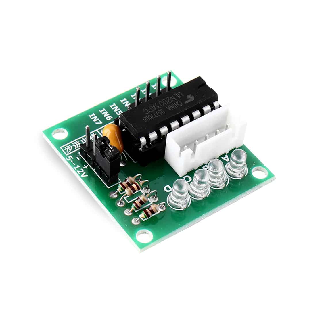
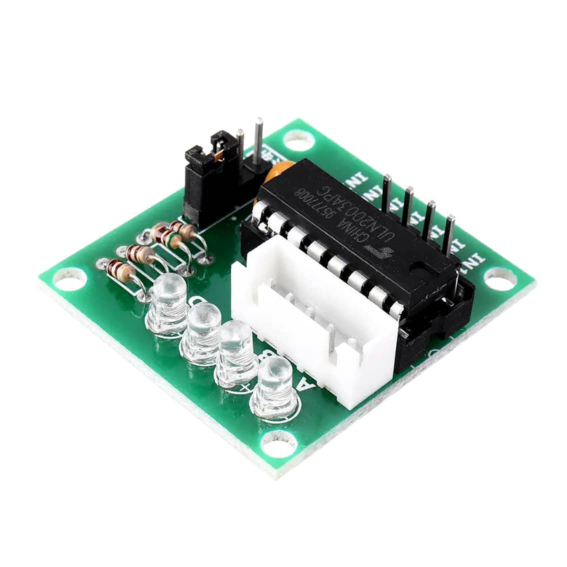
The ULN2003 driver board is designed to control unipolar stepper motors like the 28BYJ‑48. It uses the ULN2003A IC, a Darlington transistor array, to safely drive motor coils from low‑power microcontroller signals.
- Operating Voltage: 5–12V DC (commonly 5V for 28BYJ‑48)
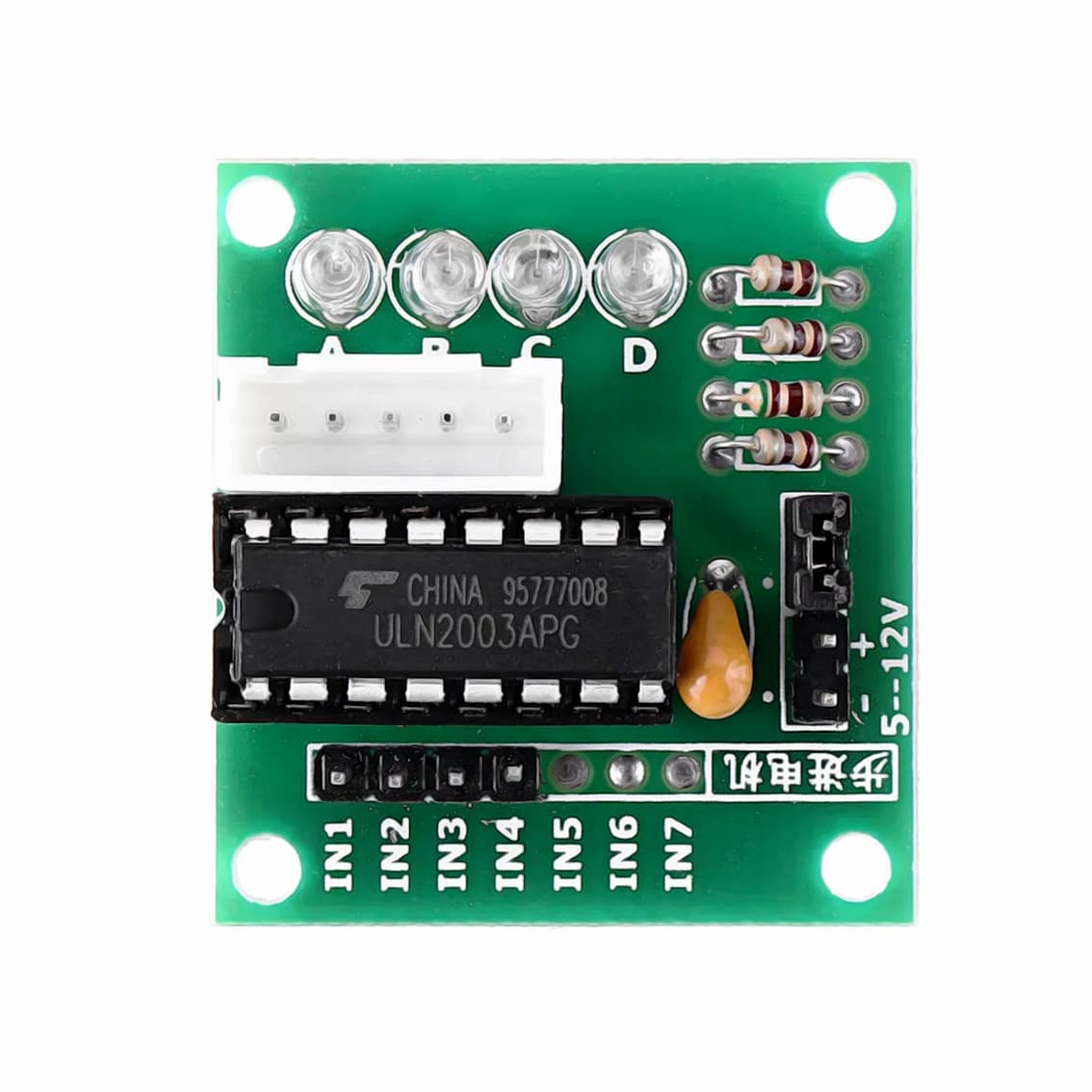
- Inputs: IN1–IN4 (sometimes IN1–IN7 exposed)
- Outputs: Motor connector (A, B, C, D coils)
- Indicators: 4 LEDs show coil activation sequence
2. Pinout
Board Connections
| Pin | Function |
|---|---|
| IN1–IN4 | Control inputs from microcontroller (Arduino, ESP32, etc.) |
| IN5–IN7 | Extra channels (not used for 28BYJ‑48, but available for other loads) |
| + | VCC (5V supply) |
| – | Ground |
| Motor Connector | White socket for 28BYJ‑48 motor wires |
Motor Connector (28BYJ‑48)
| Pin | Coil |
|---|---|
| A | Coil A |
| B | Coil B |
| C | Coil C |
| D | Coil D |
| Common | Red wire (VCC) |
3. How It Works
- The ULN2003 IC amplifies microcontroller signals to drive motor coils.
- IN1–IN4 activate coils in sequence → motor rotates step by step.
- LEDs on the board light up to show which coil is energized.
- Extra inputs (IN5–IN7) can drive other devices (LEDs, relays, buzzers).
4. Wiring Guide (Arduino Example)
- Connect + (VCC) → Arduino 5V.
- Connect – (GND) → Arduino GND.
- Connect IN1–IN4 → Arduino digital pins (e.g., D8–D11).
- Plug the motor’s white connector into the board.
5. Example Arduino Code
#include <Stepper.h>

const int stepsPerRevolution = 2048; // 28BYJ-48 motor
Stepper myStepper(stepsPerRevolution, 8, 10, 9, 11);

void setup() {
  myStepper.setSpeed(10); // RPM
}

void loop() {
  myStepper.step(stepsPerRevolution);   // one full rotation clockwise
  delay(1000);
  myStepper.step(-stepsPerRevolution);  // one full rotation counterclockwise
  delay(1000);
}
6. Applications
- Educational kits: Demonstrating stepper motor control.
- Robotics: Precise positioning for arms or wheels.
- Automation: Dials, indicators, or actuators.
- DIY projects: Rotating displays, camera sliders, tuning knobs.
7. Best Practices
- Use a regulated 5V supply for the motor.
- Only IN1–IN4 are needed for the stepper motor; IN5–IN7 are optional.
- Stepper motors draw current even when stationary → disconnect power if idle.
- For smoother motion, use half‑step or microstepping sequences.