User’s Guide: 12V 6-Channel High/Low Relay Module with Optocoupler
Overview
This module allows control of up to 6 high-voltage devices using low-voltage digital signals. It features optocoupler isolation for protection, supports high and low-level triggers, and is ideal for microcontroller integration (e.g., Arduino, STM32, ESP32).
Specifications
| Parameter | Value |
|---|---|
| Operating Voltage | 12V DC |
| Channels | 6 |
| Relay Rating | 10A @ 250V AC / 10A @ 30V DC |
| Trigger Type | High or Low Level |
| Isolation | Optocoupler per channel |
| Dimensions | 104mm × 53mm × 17mm |
| Indicators | Power LED + 6 Relay LEDs |
| Terminals | Screw terminals for I/O |
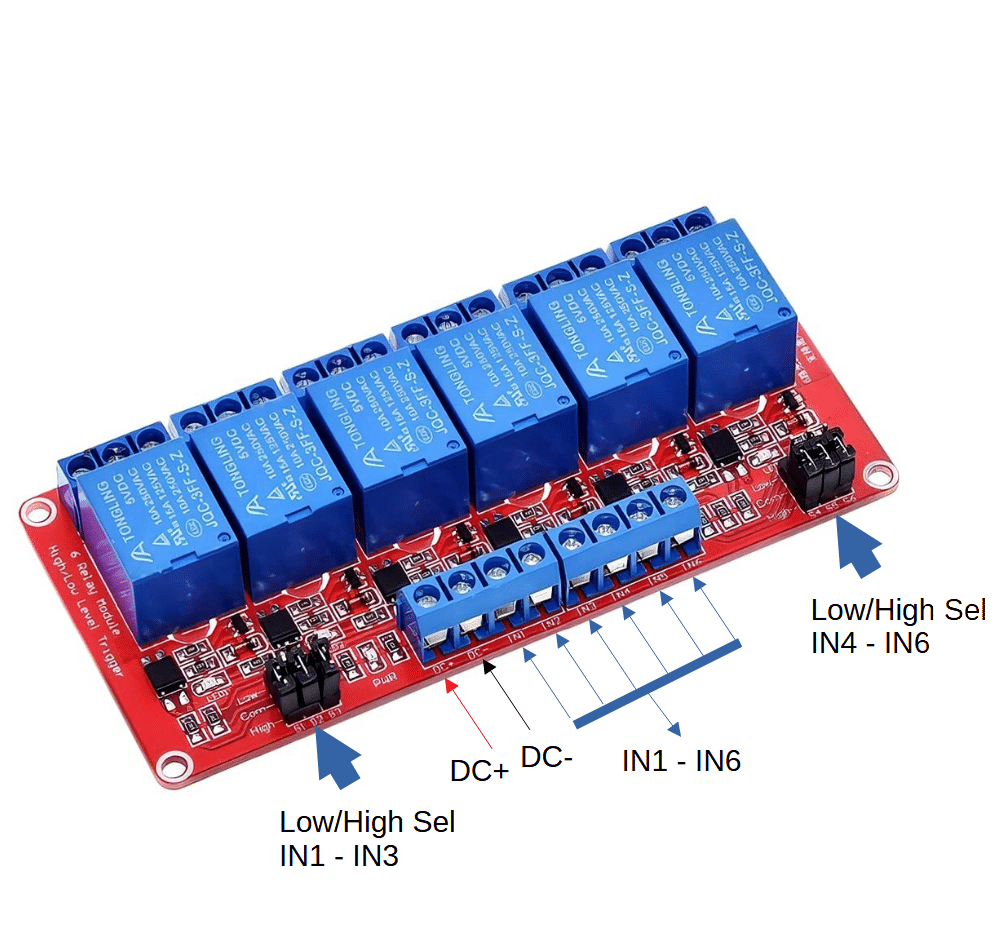
Pinout Description
| Pin Label | Function |
|---|---|
| DC+ | 12V power input |
| DC− | Ground |
| IN1–IN6 | Control signals for each relay |
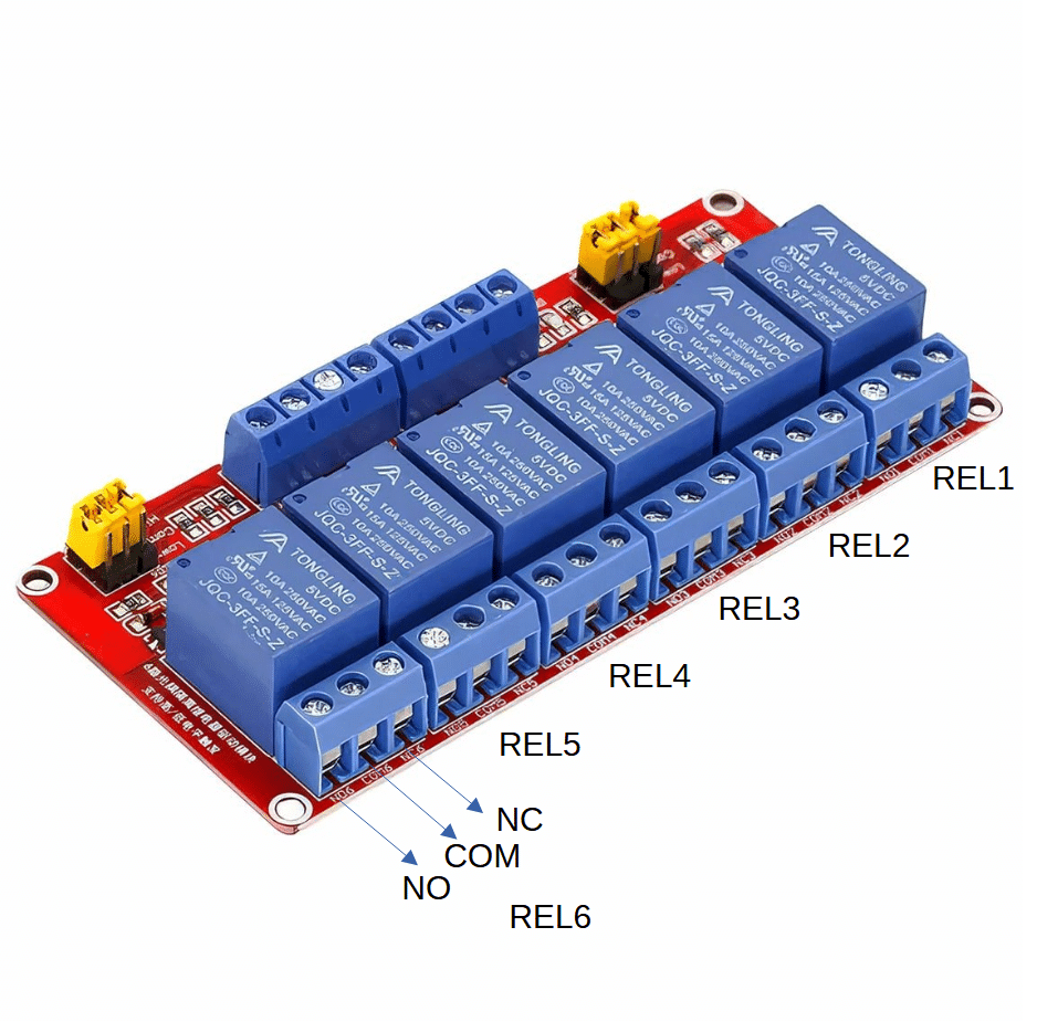
| COM, NO, NC | Relay output terminals (Common, Normally Open, Normally Closed) per channel |
Wiring Instructions
Power Supply
- Connect DC+ to +12V
- Connect DC− to GND
Control Signals
- Connect IN1–IN6 to GPIO pins of your microcontroller
- Use HIGH or LOW level trigger depending on jumper setting
Relay Output
Each relay has:
- COM: Common terminal
- NO: Normally Open (connects to COM when relay is ON)
- NC: Normally Closed (connects to COM when relay is OFF)
Trigger Mode Selection
| Jumper Position | Behavior |
|---|---|
| H (High-Level Trigger) | Relay activates when INx is HIGH |
| L (Low-Level Trigger) | Relay activates when INx is LOW |
Set jumper per channel to match your microcontroller logic level.
Example: ESP32 Control (High-Level Trigger)
ESP32 GPIO → IN1
12V → DC+
GND → DC−
Relay COM → Power Source
Relay NO → Load (e.g., fan, light)
Use digitalWrite(GPIO, HIGH) to activate relay.
Safety & Best Practices
- Use flyback diodes if switching inductive loads (motors, solenoids)
- Ensure optocoupler isolation is maintained—don’t share GND between control and load circuits unless required
- Mount securely using provided holes
- Avoid exceeding rated current/voltage per relay
Troubleshooting
| Issue | Solution |
|---|---|
| Relay LED doesn’t light | Check jumper setting and control signal logic |
| No relay click | Confirm 12V supply and INx signal level |
| Load not switching | Verify wiring to COM/NO/NC and load polarity |
Advanced Tips
- Use PWM or timed logic to pulse relays for momentary actions
- Combine with sensors (e.g., LDR, PIR) for automated switching
- Integrate with CAN bus or MQTT for remote control in IoT setups