User’s Guide for the 4 x 3 Rigid Matrix Keypad Module
## 1. Technical Overview
The keypad utilizes a matrix circuit to minimize the number of pins required on your microcontroller. Instead of 12 individual wires (one for each key), it uses a grid of 4 rows and 3 columns, requiring only 7 interface pins.
Specifications
-
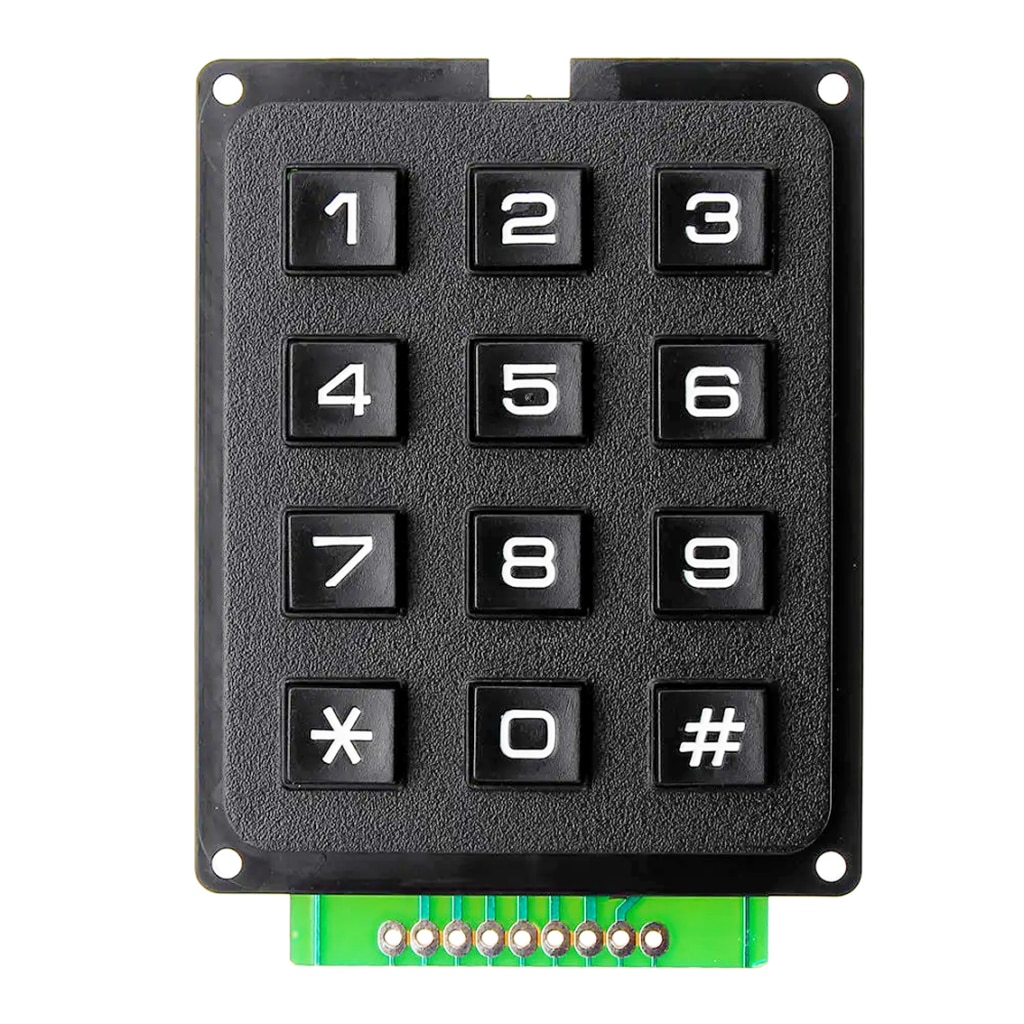
Key Layout: 0–9, *, # (12 keys total)
-
Switch Type: Tactile mechanical buttons
-
Operating Voltage: 3.0V to 12V DC
-
Pin Pitch: 2.54mm (0.1″) — Breadboard friendly
-
Dimensions: Approximately 70mm x 52mm
## 2. Pinout & Wiring Diagram
When looking at the solder pads on the bottom of the module from left to right, the standard configuration is as follows:
| Pin | Function | Associated Keys |
| 1 | Row 1 | 1, 2, 3 |
| 2 | Row 2 | 4, 5, 6 |
| 3 | Row 3 | 7, 8, 9 |
| 4 | Row 4 | *, 0, # |
| 5 | Col 1 | 1, 4, 7, * |
| 6 | Col 2 | 2, 5, 8, 0 |
| 7 | Col 3 | 3, 6, 9, # |
Note: Some variations include two extra pins on the far ends for mounting or ground shielding. Only the 7 pins connected to the green PCB traces are required for operation.
## 3. Installation & Connection
A. Hardware Setup
-
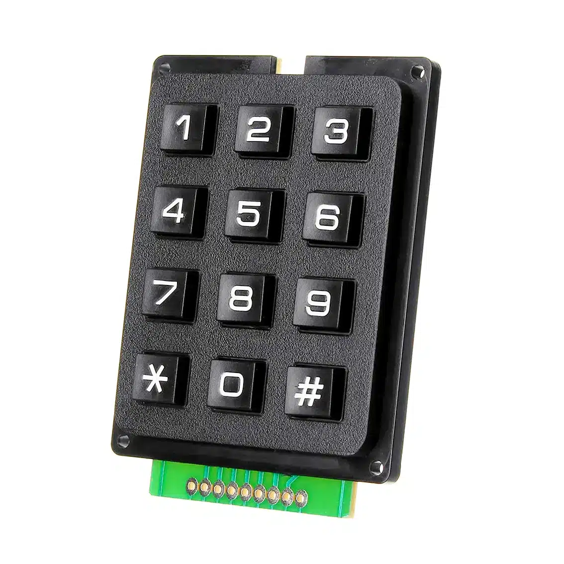
Soldering: Solder a 7-pin male header to the green PCB pads.
-
Mounting: Use the four corner mounting holes to secure the keypad to your chassis or project box.
-
Connecting to Microcontroller (e.g., Arduino):
-
Connect Row Pins (1–4) to Digital Pins 9, 8, 7, 6.
-
Connect Column Pins (5–7) to Digital Pins 5, 4, 3.
-
B. Software Setup
To read the inputs, you must use a “scanning” algorithm. For Arduino users, the Keypad.h library is recommended.
Basic Code Implementation:
#include <Keypad.h>

const byte ROWS = 4;
const byte COLS = 3;

char keys[ROWS][COLS] = {
  {'1','2','3'},
  {'4','5','6'},
  {'7','8','9'},
  {'*','0','#'}
};

byte rowPins[ROWS] = {9, 8, 7, 6};
byte colPins[COLS] = {5, 4, 3};

Keypad keypad = Keypad(makeKeymap(keys), rowPins, colPins, ROWS, COLS);

void setup() {
  Serial.begin(9600);
}

void loop() {
  char key = keypad.getKey();
  if (key) {
    Serial.println(key);
  }
}
## 4. Operating Instructions
-
Single Key Entry: Press the desired button firmly. The “tactile” click confirms the connection has been made.
-
Multiple Key Presses: This module does not support “n-key rollover.” Pressing multiple keys simultaneously may result in “ghosting,” where the controller registers an incorrect third key.
-
Cleaning: Use compressed air to remove dust between the buttons. If keys become “sticky” electronically, use a drop of 90% Isopropyl Alcohol on the switch and press it several times while powered off.
## 5. Troubleshooting
| Issue | Potential Cause | Solution |
| Wrong character appears | Row/Col pins are swapped. | Reverse the order of your wiring. |
| Key registers twice | Mechanical “bounce.” | Increase the setDebounceTime in your code. |
| One whole row fails | Broken solder joint. | Re-solder the corresponding Row pin. |
| No response | No pull-up resistors. | Ensure your code enables internal pull-ups. |