XY‑PWM / XY‑LPWM Adjustable Pulse Duty Cycle Modules User’s Guide
Frequency Range: 1Hz – 150kHz
Operating Voltage: 3.3V – 30V DC
1. Overview
These modules generate a PWM (Pulse Width Modulation) signal with adjustable frequency and duty cycle, displayed on the LCD screen.
- XY‑PWM: Basic PWM generator with push‑button control.
- XY‑LPWM: Advanced version with UART (TX/RXD) for serial communication and external control.
2. Pinout
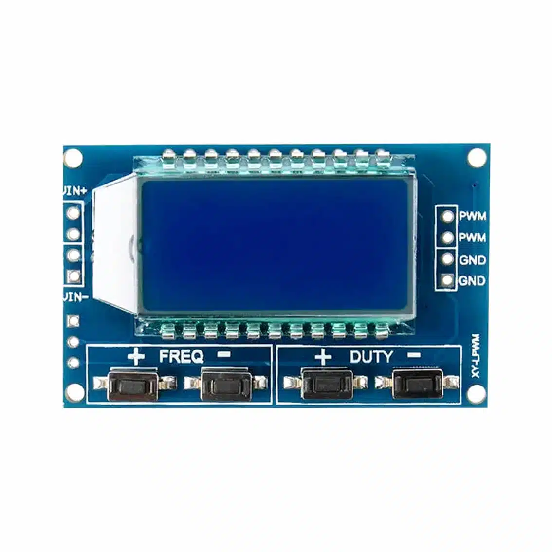
XY‑PWM Board
| Pin | Function |
|---|---|
| VIN+ | Power supply input (3.3–30V DC) |
| VIN- | Ground |
| PWM | PWM output (two pins, same signal) |
| GND | Ground (two pins) |
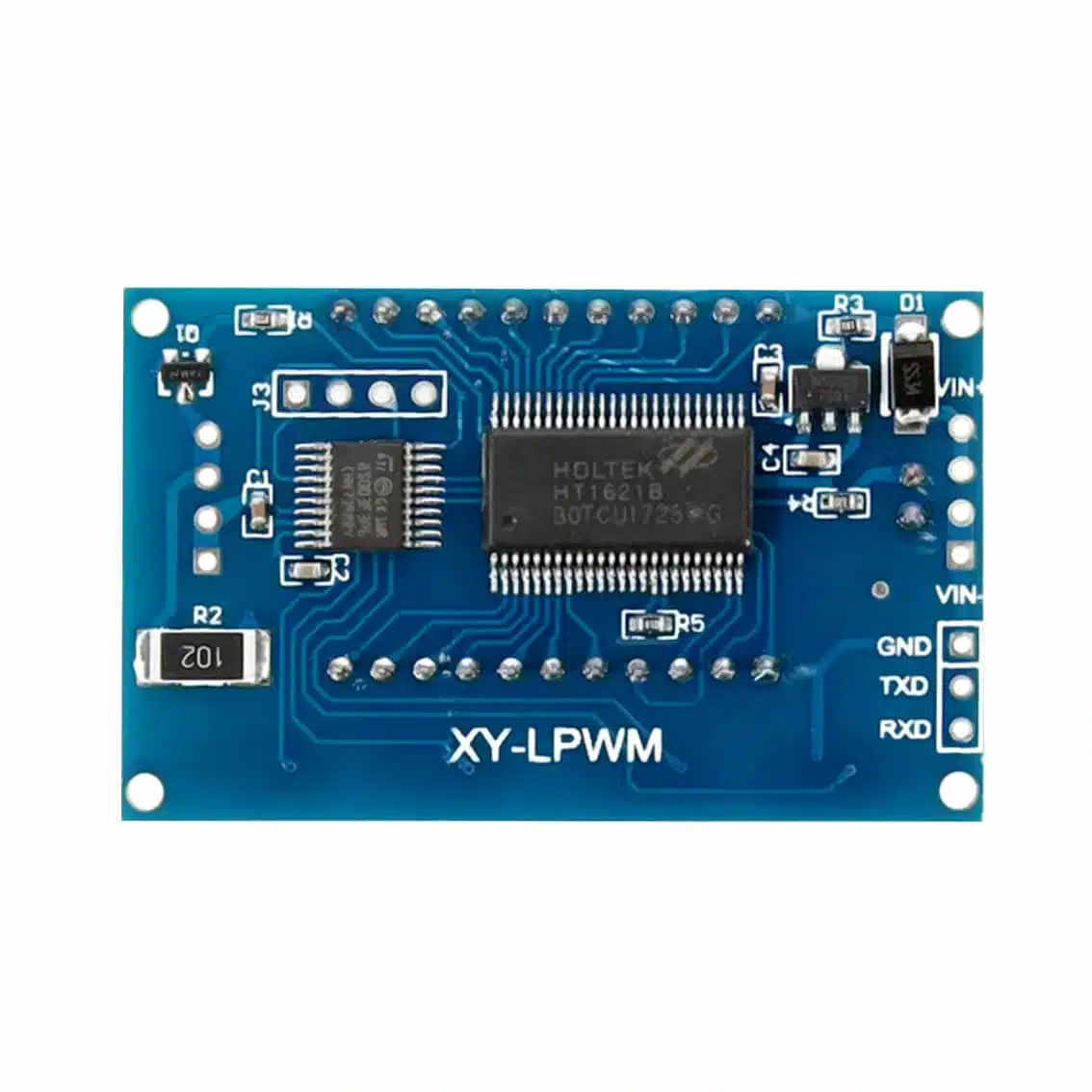
XY‑LPWM Board
| Pin | Function |
|---|---|
| VIN | Power supply input (3.3–30V DC) |
| GND | Ground |
| TXD | Serial transmit (for UART control) |
| RXD | Serial receive (for UART control) |
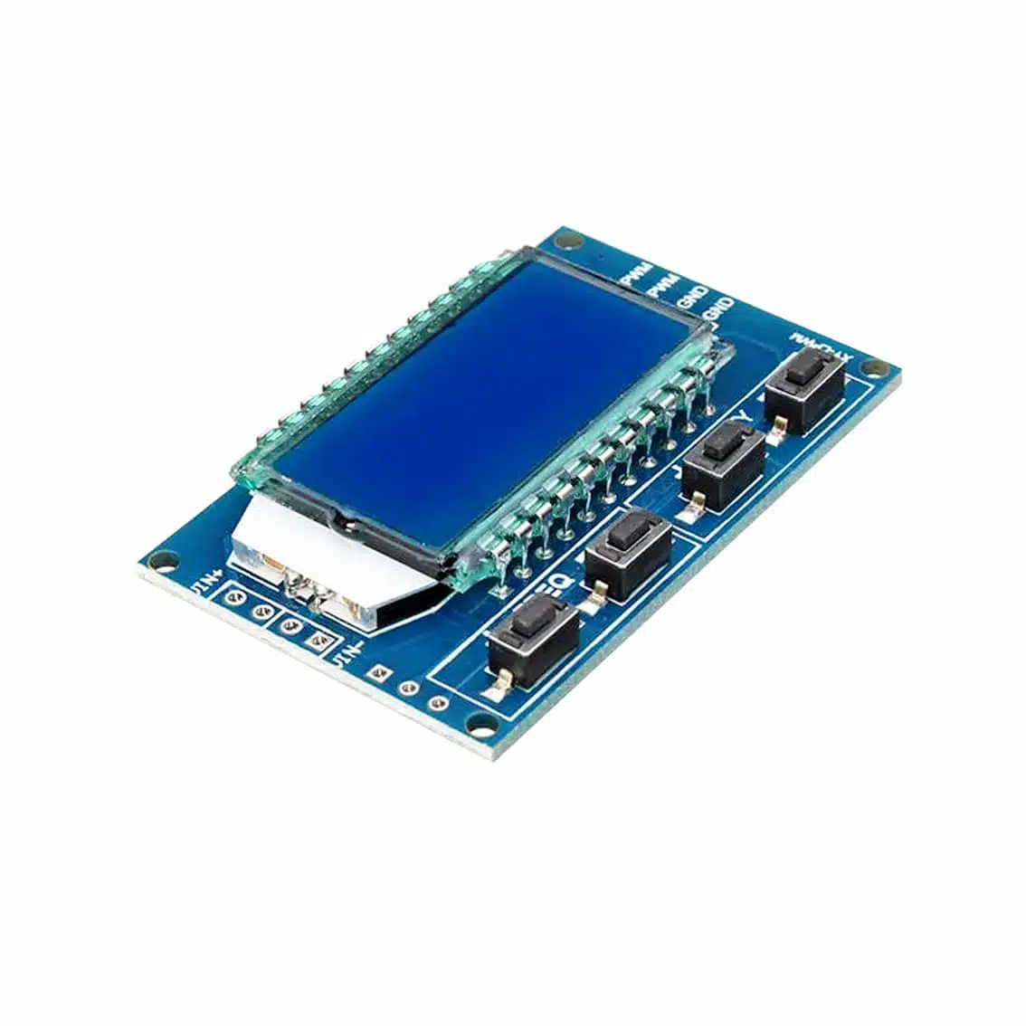
3. Controls
- LCD Display: Shows current frequency (Hz/kHz) and duty cycle (%).
- Buttons:
+ FREQ/- FREQ→ Increase/decrease frequency.+ DUTY/- DUTY→ Increase/decrease duty cycle.
On the XY‑LPWM, frequency and duty cycle can also be set via serial commands.
4. How to Use
- Power the Module
- Connect VIN+ (or VIN) to DC supply (e.g., 5V, 12V).
- Connect GND to common ground.
- Connect Output
- Use PWM pin(s) for signal output.
- Connect to motor driver, LED, or oscilloscope.
- Adjust Settings
- Use buttons to set frequency and duty cycle.
- Values update instantly on the LCD.
- (XY‑LPWM only)
- Connect TXD/RXD to a microcontroller (e.g., Arduino).
- Send UART commands to configure frequency/duty cycle remotely.
5. Example Applications
- LED Dimming: Connect PWM → resistor → LED → GND. Adjust duty cycle for brightness.
- Motor Speed Control: Feed PWM into MOSFET/motor driver. Adjust duty cycle for speed.
- Signal Testing: Use PWM as a clock or test input for digital circuits.
- Remote Control (XY‑LPWM): Adjust PWM parameters via serial commands from a microcontroller.
6. Best Practices
- Always use a driver circuit (MOSFET/transistor) for motors or high‑power loads.
- Keep supply voltage within 3.3–30V.
- For precision, verify output with an oscilloscope.
- Use proper heat dissipation if driving continuous high‑frequency loads.
7. Quick Demo Project
PWM Fan Speed Controller (XY‑PWM)
- Connect VIN+ to 12V supply, VIN- to ground.
- Connect PWM output → MOSFET gate → DC fan.
- Adjust duty cycle with buttons → fan speed changes smoothly.
- Adjust frequency → optimize for motor response (typically >20kHz for silent operation).