Here’s the final part in the STM32 UART series – Using DMA on STM32Cube IDE.
Introduction
You learned how to use basic blocking and interrupt modes on your UART devices last time. This time, you’ll learn a more sophisticated mode by using DMA. DMA stands for Dynamic Memory Access.
UART in DMA Mode
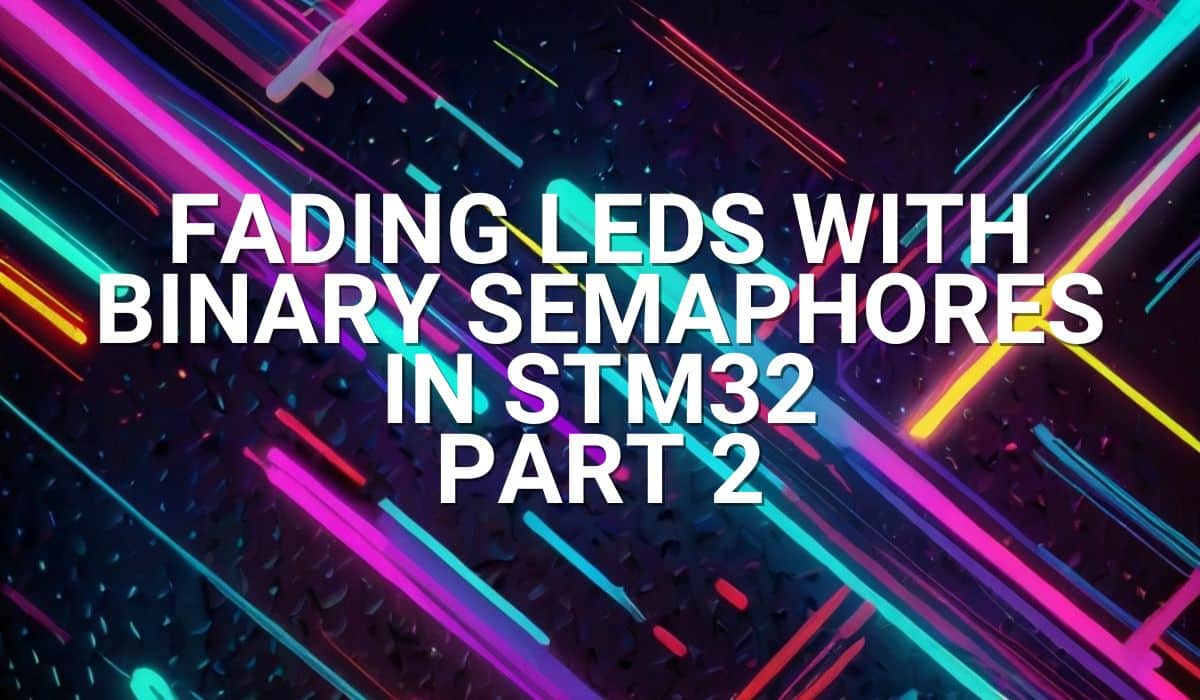
DMA spares your CPU processing time when transmitting or receiving large packets of UART data. This means your CPU shouldn’t be interrupted while doing UART transactions except in the middle or end of UART packets. Below is a block diagram of the UART peripheral for an STM32F4XX series (the one used for an STM32 Black PIll).
Above, you’ll see that the DMA controller is connected to the Memory, Peripheral, and Programming ports. UART is connected to the Peripheral port, while SRAM is connected to the Memory port. With this setup, data transfers can happen between UART and SRAM without needing CPU intervention. Additionally, you’ll see several request stream channel sources. One of these streams can be intended as a UART transmit stream, while another a receive stream. The programming port programs the behavior of the DMA block.
Example Code
UART-DMA Receive in One-Shot Mode
Here is an example of a simple UART DMA receive example in one-shot mode. One shot, meaning, you’ll have to restart the UART-DMA operation to receive another packet of data.
					/* USER CODE BEGIN Header */
/**
  ******************************************************************************
  * @file           : main.c
  * @brief          : Main program body
  ******************************************************************************
  * @attention
  *
  * Copyright (c) 2024 STMicroelectronics.
  * All rights reserved.
  *
  * This software is licensed under terms that can be found in the LICENSE file
  * in the root directory of this software component.
  * If no LICENSE file comes with this software, it is provided AS-IS.
  *
  ******************************************************************************
  */
/* USER CODE END Header */
/* Includes ------------------------------------------------------------------*/
#include "main.h"

/* Private includes ----------------------------------------------------------*/
/* USER CODE BEGIN Includes */

/* USER CODE END Includes */

/* Private typedef -----------------------------------------------------------*/
/* USER CODE BEGIN PTD */

/* USER CODE END PTD */

/* Private define ------------------------------------------------------------*/
/* USER CODE BEGIN PD */

/* USER CODE END PD */

/* Private macro -------------------------------------------------------------*/
/* USER CODE BEGIN PM */

/* USER CODE END PM */

/* Private variables ---------------------------------------------------------*/
UART_HandleTypeDef huart1;
DMA_HandleTypeDef hdma_usart1_rx;
DMA_HandleTypeDef hdma_usart1_tx;

/* USER CODE BEGIN PV */
volatile uint8_t uart_rx_flag;
/* USER CODE END PV */

/* Private function prototypes -----------------------------------------------*/
void SystemClock_Config(void);
static void MX_GPIO_Init(void);
static void MX_DMA_Init(void);
static void MX_USART1_UART_Init(void);
/* USER CODE BEGIN PFP */

/* USER CODE END PFP */

/* Private user code ---------------------------------------------------------*/
/* USER CODE BEGIN 0 */

/* USER CODE END 0 */

/**
  * @brief  The application entry point.
  * @retval int
  */
int main(void)
{

  /* USER CODE BEGIN 1 */

  /* USER CODE END 1 */

  /* MCU Configuration--------------------------------------------------------*/

  /* Reset of all peripherals, Initializes the Flash interface and the Systick. */
  HAL_Init();

  /* USER CODE BEGIN Init */

  /* USER CODE END Init */

  /* Configure the system clock */
  SystemClock_Config();

  /* USER CODE BEGIN SysInit */

  /* USER CODE END SysInit */

  /* Initialize all configured peripherals */
  MX_GPIO_Init();
  MX_DMA_Init();
  MX_USART1_UART_Init();
  /* USER CODE BEGIN 2 */

  uint8_t tx_buffer[] = "Running Code\r\n";
  uint8_t rx_buffer[20];

  // for uart-dma receive state machine
  typedef enum uart_rx_dma_mode_tag {
	  start_uart_dma_rx,
	  wait_uart_dma_rx,
  }uart_rx_dma_mode_t;

  uart_rx_dma_mode_t uart_rx_dma_mode;
  uart_rx_dma_mode = start_uart_dma_rx;

  /* USER CODE END 2 */

  /* Infinite loop */
  /* USER CODE BEGIN WHILE */
  while (1)
  {
	  switch (uart_rx_dma_mode) {
		case start_uart_dma_rx:
			// start to receive 10 UART packets in non-blocking, interrupt mode
			HAL_UART_Receive_DMA(&huart1, rx_buffer, sizeof(rx_buffer));
			// next state
			uart_rx_dma_mode = wait_uart_dma_rx;
			break;

		case wait_uart_dma_rx:
			// check uart_flag
			if(uart_rx_flag)
			{
				// received all the packets
				HAL_UART_Transmit_DMA(&huart1, rx_buffer, sizeof(rx_buffer));
				// reset flag to 0
				uart_rx_flag = 0;
				// next rx_state
				uart_rx_dma_mode = start_uart_dma_rx;

			}else{
				// same rx_state
				// proceed to run other code to make things efficient
				HAL_UART_Transmit(&huart1, tx_buffer, sizeof(tx_buffer), 10);
				// delay for demonstration
				HAL_Delay(1000);
			}
			break;
		default:
			break;
	}

    /* USER CODE END WHILE */

    /* USER CODE BEGIN 3 */
  }
  /* USER CODE END 3 */
}

/**
  * @brief System Clock Configuration
  * @retval None
  */
void SystemClock_Config(void)
{
  RCC_OscInitTypeDef RCC_OscInitStruct = {0};
  RCC_ClkInitTypeDef RCC_ClkInitStruct = {0};

  /** Configure the main internal regulator output voltage
  */
  __HAL_RCC_PWR_CLK_ENABLE();
  __HAL_PWR_VOLTAGESCALING_CONFIG(PWR_REGULATOR_VOLTAGE_SCALE1);

  /** Initializes the RCC Oscillators according to the specified parameters
  * in the RCC_OscInitTypeDef structure.
  */
  RCC_OscInitStruct.OscillatorType = RCC_OSCILLATORTYPE_HSE;
  RCC_OscInitStruct.HSEState = RCC_HSE_ON;
  RCC_OscInitStruct.PLL.PLLState = RCC_PLL_ON;
  RCC_OscInitStruct.PLL.PLLSource = RCC_PLLSOURCE_HSE;
  RCC_OscInitStruct.PLL.PLLM = 12;
  RCC_OscInitStruct.PLL.PLLN = 96;
  RCC_OscInitStruct.PLL.PLLP = RCC_PLLP_DIV2;
  RCC_OscInitStruct.PLL.PLLQ = 4;
  if (HAL_RCC_OscConfig(&RCC_OscInitStruct) != HAL_OK)
  {
    Error_Handler();
  }

  /** Initializes the CPU, AHB and APB buses clocks
  */
  RCC_ClkInitStruct.ClockType = RCC_CLOCKTYPE_HCLK|RCC_CLOCKTYPE_SYSCLK
                              |RCC_CLOCKTYPE_PCLK1|RCC_CLOCKTYPE_PCLK2;
  RCC_ClkInitStruct.SYSCLKSource = RCC_SYSCLKSOURCE_PLLCLK;
  RCC_ClkInitStruct.AHBCLKDivider = RCC_SYSCLK_DIV1;
  RCC_ClkInitStruct.APB1CLKDivider = RCC_HCLK_DIV2;
  RCC_ClkInitStruct.APB2CLKDivider = RCC_HCLK_DIV1;

  if (HAL_RCC_ClockConfig(&RCC_ClkInitStruct, FLASH_LATENCY_3) != HAL_OK)
  {
    Error_Handler();
  }
}

/**
  * @brief USART1 Initialization Function
  * @param None
  * @retval None
  */
static void MX_USART1_UART_Init(void)
{

  /* USER CODE BEGIN USART1_Init 0 */

  /* USER CODE END USART1_Init 0 */

  /* USER CODE BEGIN USART1_Init 1 */

  /* USER CODE END USART1_Init 1 */
  huart1.Instance = USART1;
  huart1.Init.BaudRate = 115200;
  huart1.Init.WordLength = UART_WORDLENGTH_8B;
  huart1.Init.StopBits = UART_STOPBITS_1;
  huart1.Init.Parity = UART_PARITY_NONE;
  huart1.Init.Mode = UART_MODE_TX_RX;
  huart1.Init.HwFlowCtl = UART_HWCONTROL_NONE;
  huart1.Init.OverSampling = UART_OVERSAMPLING_16;
  if (HAL_UART_Init(&huart1) != HAL_OK)
  {
    Error_Handler();
  }
  /* USER CODE BEGIN USART1_Init 2 */

  /* USER CODE END USART1_Init 2 */

}

/**
  * Enable DMA controller clock
  */
static void MX_DMA_Init(void)
{

  /* DMA controller clock enable */
  __HAL_RCC_DMA2_CLK_ENABLE();

  /* DMA interrupt init */
  /* DMA2_Stream2_IRQn interrupt configuration */
  HAL_NVIC_SetPriority(DMA2_Stream2_IRQn, 0, 0);
  HAL_NVIC_EnableIRQ(DMA2_Stream2_IRQn);
  /* DMA2_Stream7_IRQn interrupt configuration */
  HAL_NVIC_SetPriority(DMA2_Stream7_IRQn, 0, 0);
  HAL_NVIC_EnableIRQ(DMA2_Stream7_IRQn);

}

/**
  * @brief GPIO Initialization Function
  * @param None
  * @retval None
  */
static void MX_GPIO_Init(void)
{
  GPIO_InitTypeDef GPIO_InitStruct = {0};
/* USER CODE BEGIN MX_GPIO_Init_1 */
/* USER CODE END MX_GPIO_Init_1 */

  /* GPIO Ports Clock Enable */
  __HAL_RCC_GPIOC_CLK_ENABLE();
  __HAL_RCC_GPIOH_CLK_ENABLE();
  __HAL_RCC_GPIOA_CLK_ENABLE();

  /*Configure GPIO pin Output Level */
  HAL_GPIO_WritePin(LED_GPIO_Port, LED_Pin, GPIO_PIN_RESET);

  /*Configure GPIO pin : LED_Pin */
  GPIO_InitStruct.Pin = LED_Pin;
  GPIO_InitStruct.Mode = GPIO_MODE_OUTPUT_PP;
  GPIO_InitStruct.Pull = GPIO_NOPULL;
  GPIO_InitStruct.Speed = GPIO_SPEED_FREQ_LOW;
  HAL_GPIO_Init(LED_GPIO_Port, &GPIO_InitStruct);

/* USER CODE BEGIN MX_GPIO_Init_2 */
/* USER CODE END MX_GPIO_Init_2 */
}

/* USER CODE BEGIN 4 */
/**
  * @brief  Tx Transfer completed callbacks.
  * @param  huart  Pointer to a UART_HandleTypeDef structure that contains
  *                the configuration information for the specified UART module.
  * @retval None
  */
__weak void HAL_UART_TxCpltCallback(UART_HandleTypeDef *huart)
{
  /* Prevent unused argument(s) compilation warning */
  UNUSED(huart);
  /* NOTE: This function should not be modified, when the callback is needed,
           the HAL_UART_TxCpltCallback could be implemented in the user file
   */
}

/**
  * @brief  Tx Half Transfer completed callbacks.
  * @param  huart  Pointer to a UART_HandleTypeDef structure that contains
  *                the configuration information for the specified UART module.
  * @retval None
  */
void HAL_UART_RxCpltCallback(UART_HandleTypeDef *huart)
{
  /* Prevent unused argument(s) compilation warning */
  UNUSED(huart);
  uart_rx_flag = 1;
  /* NOTE: This function should not be modified, when the callback is needed,
           the HAL_UART_TxHalfCpltCallback could be implemented in the user file
   */
}
/* USER CODE END 4 */

/**
  * @brief  This function is executed in case of error occurrence.
  * @retval None
  */
void Error_Handler(void)
{
  /* USER CODE BEGIN Error_Handler_Debug */
  /* User can add his own implementation to report the HAL error return state */
  __disable_irq();
  while (1)
  {
  }
  /* USER CODE END Error_Handler_Debug */
}

#ifdef  USE_FULL_ASSERT
/**
  * @brief  Reports the name of the source file and the source line number
  *         where the assert_param error has occurred.
  * @param  file: pointer to the source file name
  * @param  line: assert_param error line source number
  * @retval None
  */
void assert_failed(uint8_t *file, uint32_t line)
{
  /* USER CODE BEGIN 6 */
  /* User can add his own implementation to report the file name and line number,
     ex: printf("Wrong parameters value: file %s on line %d\r\n", file, line) */
  /* USER CODE END 6 */
}
#endif /* USE_FULL_ASSERT */
Here is the code explanation: Since you are working in UART-DMA mode, it’s best to use a status flag when a UART RX DMA interrupt occurs.
					/* USER CODE BEGIN PV */
volatile uint8_t uart_rx_flag;
/* USER CODE END PV */
Same as in the UART Interrupt code, to easily integrate the UART DMA-RX ISR code in your main.c file, find the UART driver source code in the left-hand Project Explorer pane. You should see stm32f4xx_hal_uart.c inside a HAL Driver folder. Copy the __weak HAL_UART_RxCpltCallback() function to an empty code block on your main.c file, making sure you take out the __weak directive. Set the volatile global uart_rx_flag here to 1 to indicate that the UART DMA-RX interrupt occurred.
					/* USER CODE BEGIN 4 */
/**
  * @brief  Tx Half Transfer completed callbacks.
  * @param  huart  Pointer to a UART_HandleTypeDef structure that contains
  *                the configuration information for the specified UART module.
  * @retval None
  */
void HAL_UART_RxCpltCallback(UART_HandleTypeDef *huart)
{
  /* Prevent unused argument(s) compilation warning */
  UNUSED(huart);
  uart_rx_flag = 1;
  /* NOTE: This function should not be modified, when the callback is needed,
           the HAL_UART_TxHalfCpltCallback could be implemented in the user file
   */
}
/* USER CODE END 4 */
The main code of interest for receiving in DMA-UART mode is below. Like the process before, transmit and receive buffer/s are used. Here, a state machine starts the DMA UART RX and then waits for the DMA RX INT while also being capable of running other code. The DMA UART RX INT happens when all 20 UART packets are received. Note that each byte received should ideally not trigger a UART interrupt (unlike in UART Interrupt mode) that the API may handle internally. This makes the DMA-UART mode superior to the UART Interrupt mode as the CPU isn’t interrupted. After this, the program displays the receive buffer indicating that the DMA-UART RX INT event happened.
					  /* USER CODE BEGIN 2 */

  uint8_t tx_buffer[] = "Running Code\r\n";
  uint8_t rx_buffer[20];

  // for uart-dma receive state machine
  typedef enum uart_rx_dma_mode_tag {
	  start_uart_dma_rx,
	  wait_uart_dma_rx,
  }uart_rx_dma_mode_t;

  uart_rx_dma_mode_t uart_rx_dma_mode;
  uart_rx_dma_mode = start_uart_dma_rx;

  /* USER CODE END 2 */

  /* Infinite loop */
  /* USER CODE BEGIN WHILE */
  while (1)
  {
	  switch (uart_rx_dma_mode) {
		case start_uart_dma_rx:
			// start to receive 20 UART packets in non-blocking, interrupt mode
			HAL_UART_Receive_DMA(&huart1, rx_buffer, sizeof(rx_buffer));
			// next state
			uart_rx_dma_mode = wait_uart_dma_rx;
			break;

		case wait_uart_dma_rx:
			// check uart_flag
			if(uart_rx_flag)
			{
				// received all the packets
				HAL_UART_Transmit_DMA(&huart1, rx_buffer, sizeof(rx_buffer));
				// reset flag to 0
				uart_rx_flag = 0;
				// next rx_state
				uart_rx_dma_mode = start_uart_dma_rx;

			}else{
				// same rx_state
				// proceed to run other code to make things efficient
				HAL_UART_Transmit(&huart1, tx_buffer, sizeof(tx_buffer), 10);
				// delay for demonstration
				HAL_Delay(1000);
			}
			break;
		default:
			break;
	}

    /* USER CODE END WHILE */
UART-DMA Receive in Circular Buffer Mode
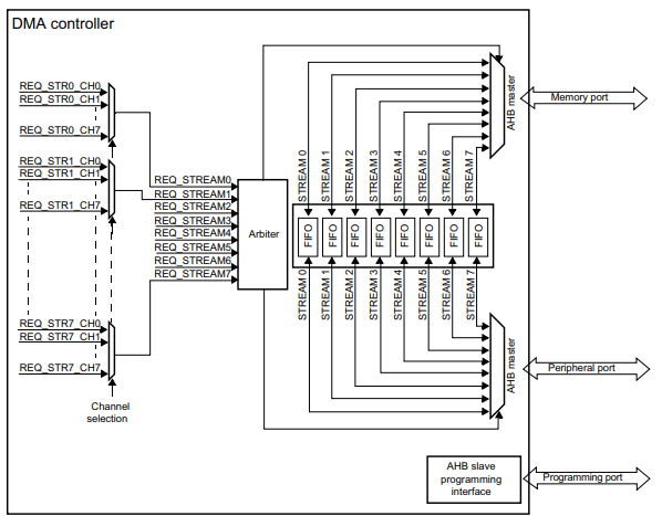
Employing a circular buffer means you don’t need to restart the UART-DMA API to acquire UART packets again. The memory slots allotted by the DMA roll over to the first memory location when all locations are filled. Programmers desire this feature to simplify acquiring serial data over and over. With this, you can just continuously wait for the UART-DMA interrupt to happen while fetching data from their DMA buffers. Don’t forget to enable this feature on your DMA settings.
					/* USER CODE BEGIN Header */
/**
  ******************************************************************************
  * @file           : main.c
  * @brief          : Main program body
  ******************************************************************************
  * @attention
  *
  * Copyright (c) 2024 STMicroelectronics.
  * All rights reserved.
  *
  * This software is licensed under terms that can be found in the LICENSE file
  * in the root directory of this software component.
  * If no LICENSE file comes with this software, it is provided AS-IS.
  *
  ******************************************************************************
  */
/* USER CODE END Header */
/* Includes ------------------------------------------------------------------*/
#include "main.h"

/* Private includes ----------------------------------------------------------*/
/* USER CODE BEGIN Includes */

/* USER CODE END Includes */

/* Private typedef -----------------------------------------------------------*/
/* USER CODE BEGIN PTD */

/* USER CODE END PTD */

/* Private define ------------------------------------------------------------*/
/* USER CODE BEGIN PD */
#define RX_BUFFER_SIZE 20
/* USER CODE END PD */

/* Private macro -------------------------------------------------------------*/
/* USER CODE BEGIN PM */

/* USER CODE END PM */

/* Private variables ---------------------------------------------------------*/
UART_HandleTypeDef huart1;
DMA_HandleTypeDef hdma_usart1_rx;
DMA_HandleTypeDef hdma_usart1_tx;

/* USER CODE BEGIN PV */
volatile uint8_t uart_rx_flag;

uint8_t tx_buffer[] = "\r\nRunning Code\r\n";
uint8_t rx_buffer[RX_BUFFER_SIZE];

/* USER CODE END PV */

/* Private function prototypes -----------------------------------------------*/
void SystemClock_Config(void);
static void MX_GPIO_Init(void);
static void MX_DMA_Init(void);
static void MX_USART1_UART_Init(void);
/* USER CODE BEGIN PFP */

/* USER CODE END PFP */

/* Private user code ---------------------------------------------------------*/
/* USER CODE BEGIN 0 */

/* USER CODE END 0 */

/**
  * @brief  The application entry point.
  * @retval int
  */
int main(void)
{

  /* USER CODE BEGIN 1 */

  /* USER CODE END 1 */

  /* MCU Configuration--------------------------------------------------------*/

  /* Reset of all peripherals, Initializes the Flash interface and the Systick. */
  HAL_Init();

  /* USER CODE BEGIN Init */

  /* USER CODE END Init */

  /* Configure the system clock */
  SystemClock_Config();

  /* USER CODE BEGIN SysInit */

  /* USER CODE END SysInit */

  /* Initialize all configured peripherals */
  MX_GPIO_Init();
  MX_DMA_Init();
  MX_USART1_UART_Init();
  /* USER CODE BEGIN 2 */


  HAL_UART_Receive_DMA(&huart1, rx_buffer, sizeof(rx_buffer));

  /* USER CODE END 2 */

  /* Infinite loop */
  /* USER CODE BEGIN WHILE */
  while (1)
  {
	  if(uart_rx_flag)
	  {
		  // continuously receive packet
		  uart_rx_flag = 0;
		  HAL_UART_Transmit_DMA(&huart1, rx_buffer, sizeof(rx_buffer));
	  }else{
		  // Do something
		  HAL_UART_Transmit_DMA(&huart1, tx_buffer, sizeof(tx_buffer));

		  HAL_Delay(100);
	  }

    /* USER CODE END WHILE */

    /* USER CODE BEGIN 3 */
  }
  /* USER CODE END 3 */
}

/**
  * @brief System Clock Configuration
  * @retval None
  */
void SystemClock_Config(void)
{
  RCC_OscInitTypeDef RCC_OscInitStruct = {0};
  RCC_ClkInitTypeDef RCC_ClkInitStruct = {0};

  /** Configure the main internal regulator output voltage
  */
  __HAL_RCC_PWR_CLK_ENABLE();
  __HAL_PWR_VOLTAGESCALING_CONFIG(PWR_REGULATOR_VOLTAGE_SCALE1);

  /** Initializes the RCC Oscillators according to the specified parameters
  * in the RCC_OscInitTypeDef structure.
  */
  RCC_OscInitStruct.OscillatorType = RCC_OSCILLATORTYPE_HSE;
  RCC_OscInitStruct.HSEState = RCC_HSE_ON;
  RCC_OscInitStruct.PLL.PLLState = RCC_PLL_ON;
  RCC_OscInitStruct.PLL.PLLSource = RCC_PLLSOURCE_HSE;
  RCC_OscInitStruct.PLL.PLLM = 12;
  RCC_OscInitStruct.PLL.PLLN = 96;
  RCC_OscInitStruct.PLL.PLLP = RCC_PLLP_DIV2;
  RCC_OscInitStruct.PLL.PLLQ = 4;
  if (HAL_RCC_OscConfig(&RCC_OscInitStruct) != HAL_OK)
  {
    Error_Handler();
  }

  /** Initializes the CPU, AHB and APB buses clocks
  */
  RCC_ClkInitStruct.ClockType = RCC_CLOCKTYPE_HCLK|RCC_CLOCKTYPE_SYSCLK
                              |RCC_CLOCKTYPE_PCLK1|RCC_CLOCKTYPE_PCLK2;
  RCC_ClkInitStruct.SYSCLKSource = RCC_SYSCLKSOURCE_PLLCLK;
  RCC_ClkInitStruct.AHBCLKDivider = RCC_SYSCLK_DIV1;
  RCC_ClkInitStruct.APB1CLKDivider = RCC_HCLK_DIV2;
  RCC_ClkInitStruct.APB2CLKDivider = RCC_HCLK_DIV1;

  if (HAL_RCC_ClockConfig(&RCC_ClkInitStruct, FLASH_LATENCY_3) != HAL_OK)
  {
    Error_Handler();
  }
}

/**
  * @brief USART1 Initialization Function
  * @param None
  * @retval None
  */
static void MX_USART1_UART_Init(void)
{

  /* USER CODE BEGIN USART1_Init 0 */

  /* USER CODE END USART1_Init 0 */

  /* USER CODE BEGIN USART1_Init 1 */

  /* USER CODE END USART1_Init 1 */
  huart1.Instance = USART1;
  huart1.Init.BaudRate = 115200;
  huart1.Init.WordLength = UART_WORDLENGTH_8B;
  huart1.Init.StopBits = UART_STOPBITS_1;
  huart1.Init.Parity = UART_PARITY_NONE;
  huart1.Init.Mode = UART_MODE_TX_RX;
  huart1.Init.HwFlowCtl = UART_HWCONTROL_NONE;
  huart1.Init.OverSampling = UART_OVERSAMPLING_16;
  if (HAL_UART_Init(&huart1) != HAL_OK)
  {
    Error_Handler();
  }
  /* USER CODE BEGIN USART1_Init 2 */

  /* USER CODE END USART1_Init 2 */

}

/**
  * Enable DMA controller clock
  */
static void MX_DMA_Init(void)
{

  /* DMA controller clock enable */
  __HAL_RCC_DMA2_CLK_ENABLE();

  /* DMA interrupt init */
  /* DMA2_Stream2_IRQn interrupt configuration */
  HAL_NVIC_SetPriority(DMA2_Stream2_IRQn, 0, 0);
  HAL_NVIC_EnableIRQ(DMA2_Stream2_IRQn);
  /* DMA2_Stream7_IRQn interrupt configuration */
  HAL_NVIC_SetPriority(DMA2_Stream7_IRQn, 0, 0);
  HAL_NVIC_EnableIRQ(DMA2_Stream7_IRQn);

}

/**
  * @brief GPIO Initialization Function
  * @param None
  * @retval None
  */
static void MX_GPIO_Init(void)
{
  GPIO_InitTypeDef GPIO_InitStruct = {0};
/* USER CODE BEGIN MX_GPIO_Init_1 */
/* USER CODE END MX_GPIO_Init_1 */

  /* GPIO Ports Clock Enable */
  __HAL_RCC_GPIOC_CLK_ENABLE();
  __HAL_RCC_GPIOH_CLK_ENABLE();
  __HAL_RCC_GPIOA_CLK_ENABLE();

  /*Configure GPIO pin Output Level */
  HAL_GPIO_WritePin(LED_GPIO_Port, LED_Pin, GPIO_PIN_RESET);

  /*Configure GPIO pin : LED_Pin */
  GPIO_InitStruct.Pin = LED_Pin;
  GPIO_InitStruct.Mode = GPIO_MODE_OUTPUT_PP;
  GPIO_InitStruct.Pull = GPIO_NOPULL;
  GPIO_InitStruct.Speed = GPIO_SPEED_FREQ_LOW;
  HAL_GPIO_Init(LED_GPIO_Port, &GPIO_InitStruct);

/* USER CODE BEGIN MX_GPIO_Init_2 */
/* USER CODE END MX_GPIO_Init_2 */
}

/* USER CODE BEGIN 4 */
/**
  * @brief  Tx Half Transfer completed callbacks.
  * @param  huart  Pointer to a UART_HandleTypeDef structure that contains
  *                the configuration information for the specified UART module.
  * @retval None
  */
void HAL_UART_RxCpltCallback(UART_HandleTypeDef *huart)
{
  /* Prevent unused argument(s) compilation warning */
  UNUSED(huart);
  uart_rx_flag = 1;
  /* NOTE: This function should not be modified, when the callback is needed,
           the HAL_UART_TxHalfCpltCallback could be implemented in the user file
   */
}


/* USER CODE END 4 */

/**
  * @brief  This function is executed in case of error occurrence.
  * @retval None
  */
void Error_Handler(void)
{
  /* USER CODE BEGIN Error_Handler_Debug */
  /* User can add his own implementation to report the HAL error return state */
  __disable_irq();
  while (1)
  {
  }
  /* USER CODE END Error_Handler_Debug */
}

#ifdef  USE_FULL_ASSERT
/**
  * @brief  Reports the name of the source file and the source line number
  *         where the assert_param error has occurred.
  * @param  file: pointer to the source file name
  * @param  line: assert_param error line source number
  * @retval None
  */
void assert_failed(uint8_t *file, uint32_t line)
{
  /* USER CODE BEGIN 6 */
  /* User can add his own implementation to report the file name and line number,
     ex: printf("Wrong parameters value: file %s on line %d\r\n", file, line) */
  /* USER CODE END 6 */
}
#endif /* USE_FULL_ASSERT */
With this, you don’t have to make a complex state machine to receive your UART packets continuously.
					  /* Infinite loop */
  /* USER CODE BEGIN WHILE */
  while (1)
  {
	  if(uart_rx_flag)
	  {
		  // continuously receive packet
		  uart_rx_flag = 0;
		  HAL_UART_Transmit_DMA(&huart1, rx_buffer, sizeof(rx_buffer));
	  }else{
		  // Do something
		  HAL_UART_Transmit_DMA(&huart1, tx_buffer, sizeof(tx_buffer));

		  HAL_Delay(100);
	  }

    /* USER CODE END WHILE */

    /* USER CODE BEGIN 3 */
  }
  /* USER CODE END 3 */
However, a really powerful use case of using a DMA circular buffer is continuously acquiring data using dual buffers; while one buffer receives the data, the other can be worked on already. A practical use case for high-speed ADCs.
SHOP THIS PROJECT
-
Sale!

Digital LCD Thermometer Temperature Gauge with Probe
$15.95Original price was: $15.95.$14.95Current price is: $14.95. Add to cart