ADJUSTABLE AD620 SMALL SIGNAL AMPLIFIER MODULE USERS GUIDE
Overview
This module is a high-precision uV / mV voltage amplifier or small signal instrumentation amplifier based on the AD620 IC from Analog Devices. With the said chip, the module can amplify uV and mV AC or DC voltages. Additionally, you can adjust the zero-level offset of your output signal to improve the accuracy of your project waveforms. Internally, this module creates a split power supply from your DC supply to adjust the offset of your output signal. The split power output is available to the user with the V- terminal as negative supply.
Product Image and Label
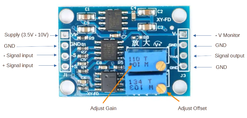
How to Use this Module
- First supply a DC source to the Vin and GND at the input terminals. This will power up the module. For better linearity, adjust your power supply to approximately 3 – 10V.
Adjust the Output Offset Voltage
- Short the input -S and +S terminals
- Put an Oscilloscope or Voltmeter on Vout and Gnd output terminals.
- Adjust the Adjust Offset Potentiometer. Make it zero to get a zero-offset voltage.
Single-Ended Measurements
- Put your signal to amplify to the +S signal input terminal.
- Put the GND of your signal to the -S signal input terminal.
- Check the Vout output with your scope or voltmeter. You can adjust the amplitude of your waveform using the Adjust Gain pot.
Differential Measurements
- Put your +signal to the +S signal input terminal.
- Put your -signal to the -S signal input terminal.
- Check the Vout output with your scope or voltmeter. You can adjust the amplitude of your waveform using the Adjust Gain pot.