Phipps Electronics

Order within the next 

FREE SHIPPING OVER $199

50,000+ ORDERS

WORLDWIDE SHIPPING

SSL SECURED

Basic ADC on ATTiny85 using Arduino

Contents

Read this article to learn about basic ADC functions on an ATTiny85 on Arduino. Get ready to read your analog values using this tiny inexpensive off-the-shelf microcontroller.

Introduction

An ADC is a standard peripheral on a microcontroller nowadays. Keeping the ADC inside a tiny microcontroller (such as the ATTiny85) makes the device indispensable for space-constrained applications. Another thing to consider is cost. Imagine trying to gather battery-level data inside a compact device (such as a power bank); the ATTiny85 can be a valuable tool for this application. Additionally, you can run the ADC of the ATTiny85 on the Arduino IDE. 

The ATTiny85 ADC

ATTiny85 ADC Block Diagram

The ATTiny85 is a SAR (successive approximation) type ADC with a maximum 10-bit resolution. It can function as four multiplexed single-ended or two differential inputs. The ADC input voltage range can be set from 0 to Vcc or through an external or internal voltage reference. You may use it in single or free-running conversion mode. The ADC can work in sleep or idle mode with noise noise-cancelling feature. The ADC start of conversion can be started manually, with auto triggering, or through interrupt sources.

The next part will discuss how to program an ADC on an ATTiny85. You can go through How to Program an ATTiny85 with an Arduino if you haven’t yet.

Program an ATTiny85 ADC using Arduino UNO
ATtiny85 Pinout

StarT with a Simple ADC Conversion

Here, you’ll learn the simplest form of ADC conversion which is a single channel that’s started by the user. The statements will be explained step by step.

				
					#include <avr/io.h>
#include <SoftwareSerial.h>

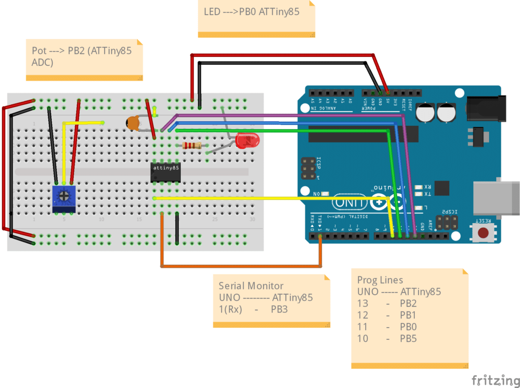
SoftwareSerial Monitor(4, 3); // 4 is Rx, 3 is Tx

uint16_t adc_value;
uint8_t toggle;

void setup() {
  // put your setup code here, to run once:
  pinMode(3, OUTPUT);   // Tx
  pinMode(4, INPUT);    // Rx
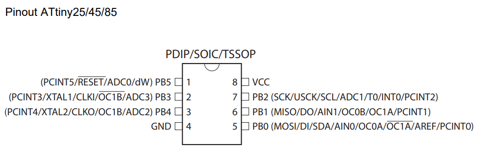
  pinMode(0,OUTPUT);    // LED

  Monitor.begin(9600);

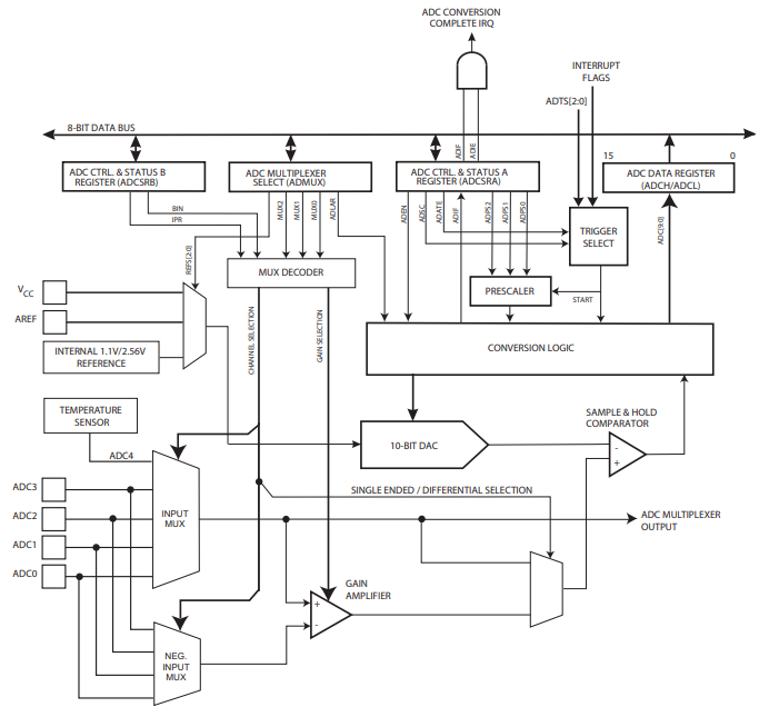
  // ADC Left Shift Result
  ADMUX |= 1<<ADLAR;
  
  // ADC Voltage Referrence
  ADMUX |= 0<<REFS2|0<<REFS1|0<<REFS0;        // Vcc is used as Voltage Referrence

  // ADC Input Channel/s
  ADMUX |= 0<<MUX3|0<<MUX2|0<<MUX1|1<<MUX0;   // Use ADC1 on pin PB2 as ADC input

  // ADC clock prescaler
  ADCSRA |= 0<<ADPS2|1<<ADPS1|1<<ADPS0;       // Use a divide by 8 Prescaler.
                                              // Sysclock = 8MHz, ADCclk = 1MHz (max)

  ADCSRA |= 1<<ADEN;                          // Enable the ADC                           

}

void loop() {

  ADCSRA |= 1<<ADSC;                          // Start the ADC conversion

  while(ADCSRA &(1<<ADCS) == 1);            // wait until conversion is finished. 
                                              // a 0 on ADCSRA means conversion is complete
  
  adc_value = ADCL|(ADCH << 8);               // ADC value is left justified. Use operand precedence rules 
                                              // left to right precedence, so ADCL is read first

  Monitor.print("10-bit ADC value is: ");
  Monitor.println(adc_value);

  toggle ^= 1;
  digitalWrite(0, toggle);
  delay(1000);

}


Since the ATTiny85 has no hardware UART, the SoftwareSerial library is included. This allows the user to check ADC values through a serial monitor. However, note that another board (an Arduino UNO that is) is used for the serial monitoring.

In the setup code, pins 3 and 4 are for the Serial Monitor while pin 0 is for a test LED. Pin 3 of the ATTiny85 can connect to pin 1 (UART Rx) of an Arduino UNO for serial monitoring.

*Note, you may use the same Arduino board as ISP and serial monitor for your ATTiny85. However, the Arduino as ISP example program does not seem to have serial monitor functionality. With this, you may have to re-program the UNO with another skecth (such as the Blinky sketch) to get the serial monitor going. Make sure to take off the serial monitor pins during programming.

Steps to Setup the ADC

  1. Set up the format of the ADC result (ADCH and ADCL registers). Here, a 10-bit format is used with left justification through the ADLAR register in ADMUX.
  2. Specify the ADC input channel. ADC1 on pin PB2 is used here through the MUXn bits in the ADMUX register.
  3. Set the clock prescaler for the ADC. The ADC conversion clock can only go as high as 1MHz. Set it through the ADPSn bits in the ADCSRA register.
  4. Enable the ADC through the ADEN bit.

After setting up, you can now make single conversions on the ADC in the loop code.

Steps to MAke Single ADC Conversions

  1.  Start the ADC conversion by setting the ADSC bit in the ADCSRA register.
  2.  Monitor the ADSC bit until it becomes a zero. This means the ADC has finished conversion.
  3.  You may now extract the value of the ADCL and ADCH registers and put it into your ADC variable (The 16-bit adc_value here). Note that there’s a two-step approach to get a 10-bit value from your 8-bit microcontroller. First, get the ADCL and then the ADCH value. After that, combine them. However, this example combined the process through operand precedence rules (left-to-right).

Now you can use or print your ADC value in a serial monitor (on another Arduino) to verify its value. Remember to disconnect the programming line PB2 if it’s populated on your ADC pin and replace it with a potentiometer.

Circuit in Action

SUBSCRIBE FOR NEW POST ALERTS

Subscribe to be the first to know when we publish a new article!
List Subscriptions(Required)

POPULAR POSTS

Scroll to Top