Read this article to learn how to program an ATtiny85 microcontroller through an Arduino as an ISP in the Arduino IDE.
Introduction
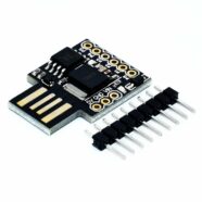
An ATtiny microcontroller is a versatile microcontroller in a small form factor. You’ll see several versions of this microcontroller and the ATtiny85 is the classic and probably most popular one (there are actually newer versions of the ATtiny series that came out like the tinyAVR 0 and 1-series). You’re sure to find several projects utilizing theATtiny85 chip. With this, you won’t regret having this microcontroller at hand.
However, in order to get the most out of the ATtiny85, you should learn to work with it in the Arduino IDE. Using Arduino style coding simplifies things and makes open-source projects easier to find. Additionally, knowing how to program this tiny chip using already available Arduino hardware (such as an UNO or Nano) makes things easier for an electronics hobbyist.
ThingS You'll Need
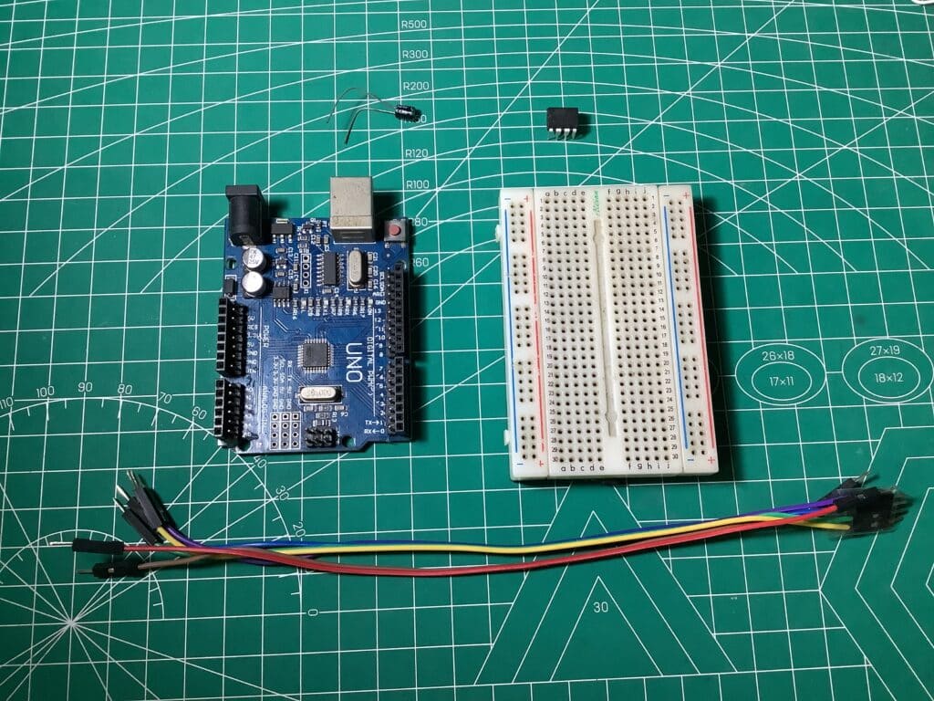
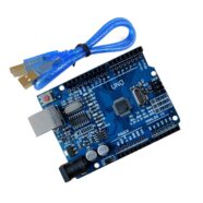
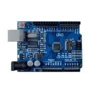
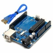
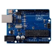
An Arduino UNO or Nano or something similar
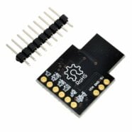
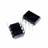
Your ATtiny85 chip
Connecting wires
A 10uF (or something close) electrolytic capacitor
Your breadboard
Optional (resistor and led) for Blinky test
The Arduino UNO will be an ISP (In System Programmer) for the ATtiny85. This means that, initially, the ATtiny85 will be programmed by the Arduino UNO hardware first. The ATtiny85 cannot be programmed directly from your PC port without a hardware programmer first because it does not have a bootloader installed.
Connections
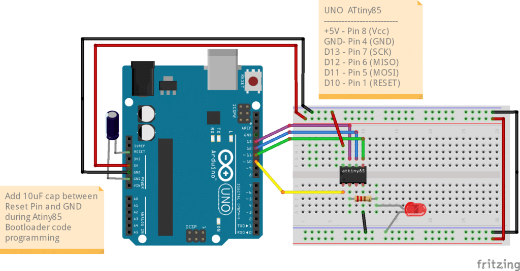
Follow the the circuit above to connect your UNO to your ATtiny85. You’ll see the connection uses SPI. Note the 10uF cap placed between the reset pin of the UNO and GND. This component is needed during programming the bootloader code to the ATtiny so that the correct sequence of bootup happens during the reset state of the programming sequence.
Install the ATtiny Board files
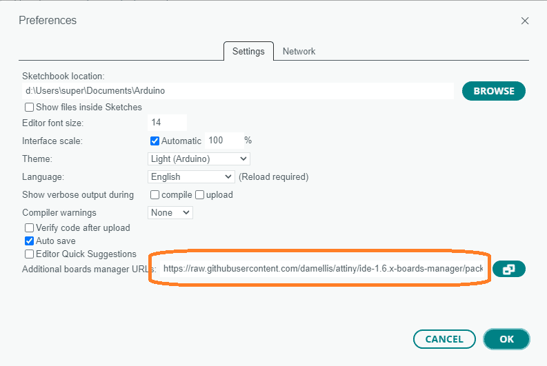
Go to File -> Preferences and enter the board file pack in the Additional boards manager URL:
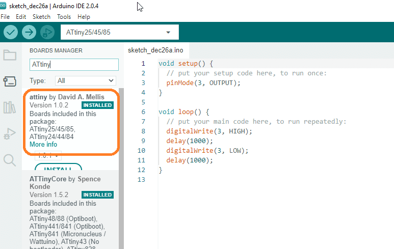
After this step, make sure you install the ATtiny board in your Tools -> Board Manager so that you can choose the board later.
Get youR Arduino Ready to become an ISP
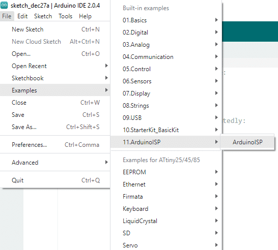
Your Arduino UNO, Nano, or other Arduino hardware can act as In-System-Programmer to program bare chips such as the ATtiny85. You don’t need to buy a separate hardware programmer. Simply open the example file called Arduino as ISP and then burn it to your Arduino UNO.
(Note: If you do decide you want a dedicated hardware programmr, you can choose from the list below:)
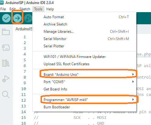
Make sure you’ve chosen your Arduino UNO together with its port as board. Also choose the Programmer as AVRISP mkll. Note that at this point, you should take out the 10uF electrolytic capacitor to have a normal reset sequence while programming the UNO. Next, click upload to program the Arduino as ISP code.
Program your Attiny85 with Bootloader code
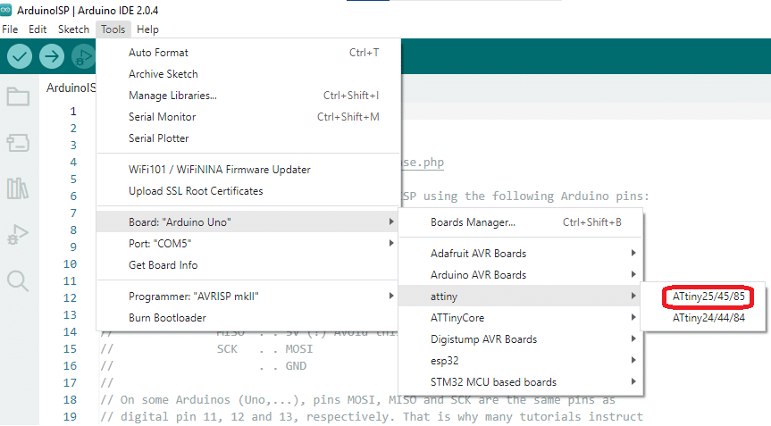
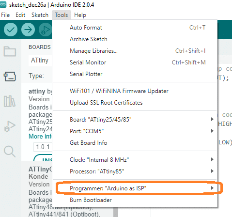
You can now choose your ATtiny85 chip as the chip to program the bootloader. In Tools, go to Boards, then Choose attiny -> ATtiny/25/45/85.
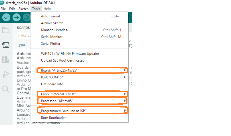
Additionally, enter the parameters below to correctly run the bootloader code. The Board should be ATtiny25/45/85. Next, choose a clock speed. Here, Internal 8MHz is chosen. The processor is ATtiny85 and the Programmer is Arduino as ISP.
Make sure you install the 10uF electrolytic cap at this point. After this, choose Burn Bootloader to proceed programming the bootloader to your Attiny85 chip. It should say “Done Burning the Bootloader”.
Program any Code to your ATtiny85
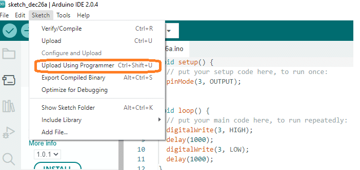
It’s now super easy to program any code to your ATtiny85. Just make sure you choose the same settings above in Tools (You can actually choose a different clock rate). At the same time, choose Upload using Programmer as Upload Method when uploading. At this point, it’s probably fine to take out the 10uF cap as we checked.
Try it out with this simple Blinky program. Digital pin 3 is used here for the test.
					void setup() {
  // put your setup code here, to run once:
  pinMode(3, OUTPUT);
}

void loop() {
  // put your main code here, to run repeatedly:
  digitalWrite(3, HIGH);
  delay(1000);
  digitalWrite(3, LOW);
  delay(1000);
}