Phipps Electronics

Order within the next 

FREE SHIPPING AUSTRALIA WIDE

50,000+ ORDERS

WORLDWIDE SHIPPING

SSL SECURED

Multiple ADC channels on an ATTiny85

Contents

Read this blog to be able to read multiple ADC channels on an ATtiny85.

Introduction

Last time, you learned how to use a basic ADC channel and program it on an ATTiny85. The process involves selecting parameters such as the ADC ref, ADC clock and prescaler, results format, and the ADC channel. This time, you’ll learn to read multiple ADC channels on your ATTiny85.

ready your Multiple ADC Channel Circuit

ATTiny85 ADC Multiple Channel Set up
ATtiny85 Pinout

Above you have a circuit with 3 potentiometers connected to ADC1(PB2), ADC2(PB4), and ADC3(PB3) of the ATTiny. A serial port is simulated through software on the ATTiny Tx line PB0 which connects to pin 1 of the UNO. The usual programming lines pin 13, 12, 11, and 10 of the UNO connects to PB2, PB1, PB0, and PB5 of the ATTiny, 

The Program

				
					#include <avr/io.h>
#include <SendOnlySoftwareSerial.h>


uint16_t adc_value;
uint8_t i;

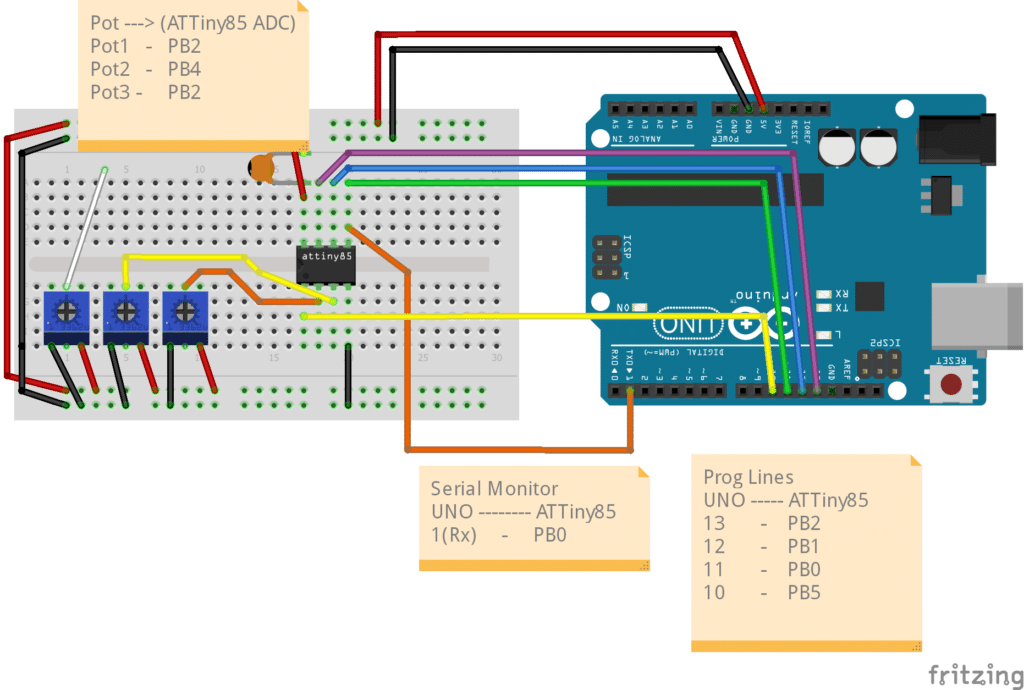
SendOnlySoftwareSerial Monitor (0);  // use PB0 as Tx Pin

void setup() {
  // put your setup code here, to run once:

  // disable digital input
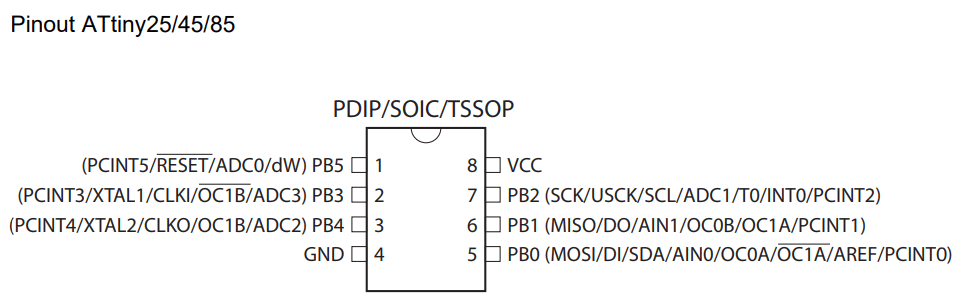
  DIDR0 |= (1<<ADC0D)|(1<<ADC2D)|(1<<ADC3D)|(1<<ADC1D);
  
  // Start the Software Serial Monitor
  Monitor.begin(9600);

  // ADC Left Shift Result
  ADMUX |= (1<<ADLAR)|
  
  // ADC Voltage Referrence
            (0<<REFS2)|(0<<REFS1)|(0<<REFS0);        // Vcc is used as Voltage Referrence


  // ADC clock prescaler
  ADCSRA |= (0<<ADPS2)|(1<<ADPS1)|(1<<ADPS0)|       // Use a divide by 8 Prescaler.
                                                    // Sysclock = 8MHz, ADCclk = 1MHz (max)
  
            (1<<ADEN);                              // Enable the ADC                           
}

void loop() {

  // Select ADC Channel
  for(i=0;i<3;i++)
  {
    ADMUX &= B11110000; // clear MUXn bits

    switch (i) {
      case 0:
        // ADC Input Channel/s
        ADMUX |= (0<<MUX3)|(0<<MUX2)|(1<<MUX1)|(0<<MUX0);   // Use ADC2 on pin PB4 as ADC input
        break;
      case 1:
        // ADC Input Channel/s
        ADMUX |= (0<<MUX3)|(0<<MUX2)|(1<<MUX1)|(1<<MUX0);   // Use ADC3 on pin PB3 as ADC input
        break;
      case 2:
        // ADC Input Channel/s
        ADMUX |= (0<<MUX3)|(0<<MUX2)|(0<<MUX1)|(1<<MUX0);   // Use ADC1 on pin PB2 as ADC input
        break;

      default:
        break;

    }
  

    ADCSRA |= (1<<ADSC);                          // Start the ADC conversion

    while(ADCSRA &(1<<ADSC) == 1);                // wait until conversion is finished. 
                                                    // a 0 on ADCSRA means conversion is complete
    ADCSRA |= (1<<ADIF);                          // Clear ADC flag

    adc_value = ADCL|(ADCH << 8);                 // ADC value is left justified. Use operand precedence rules 
                                                    // left to right precedence, so ADCL is read first
    Monitor.print("10-bit ADC");
    Monitor.print(i+1); 
    Monitor.print(" value is: ");
    Monitor.println(adc_value);
      
    delay(1000);
  }

  Monitor.println();

}


The firmware consists of the usual ADC setup only now, the MUXn bits of the ADMUX registers are manipulated in the looping code. Also, a SendOnlySoftwareSerial monitor library is used instead of SoftwareSerial to eliminate the need for an RX pin. This process keeps other pins available on the ATTiny.

Steps to Setup the ADC

There are lots of similarities in setting up the ADC like in the previous blog. However, in this setup, you specify the ADC channel to use before starting the ADC conversion (or after finishing it according to the datasheet). The MUXn bits in the ADMUX register are scanned before (or after) conversions as they are locked during the conversion process. This protects the integrity of your ADC data.

  1. There is an optional step to disable the digital inputs ADC0D – ADC3D in the DIDR0 register to save power generated by the digital input buffer.
  2. Begin the SendOnlySoftwareSerial Instance Monitor and set it to your desired baud rate.
  3. Set up the format of the ADC result (ADCH and ADCL registers). Here, a 10-bit format is used with left justification through the ADLAR register in ADMUX.
  4. Set the clock prescaler for the ADC. The ADC conversion clock can only go as high as 1MHz. Set it through the ADPSn bits in the ADCSRA register.
  5. Enable the ADC through the ADEN bit.

Steps to Make Multiple ADC Channel Conversions

After setup, you can now go through the looping code.

  1. Select the ADC channel you want to use by clearing the MUXn bits and then setting them on the ADMUX register. (Note that the order of the conversions seems one step behind in actual. It could be the MUXn bits were actually relayed after the conversion process).
  2. Start the ADC conversion by setting the ADSC bit in the ADCSRA register.
  3. Monitor the ADSC bit until it becomes zero. This means the ADC has finished conversion.
  4. You may now extract the value of the ADCL and ADCH registers and put it into your ADC variable (The 16-bit adc_value here). Note that there’s a two-step approach to get a 10-bit value from your 8-bit microcontroller. First, get the ADCL and then the ADCH value. After that, combine them. However, this example combined the process through operand precedence rules (left-to-right).
  5. The process repeats in a for-loop so that you can scan the 3 ADC channels consecutively.

The programming process starts with the Arduino UNO programmed as an Arduino ISP as in the previous blog and continues from there. To do serial monitoring, you can use the same Arduino UNO provided that you program it with a blank or blinky code that has serial monitor capability. Make sure to disconnect the serial monitor pins while programming. Also, disconnect programming lines that may interfere with your ADC readings.

Hope you’ve learned a lot on this topic about multiple ADC channels on an ATTiny85 tutorial :).

Circuit in Action

Upload ISP code to UNO

Upload using programmer to ATtiny85  

Program Blinky Code to UNO and Start Serial Monitor 

Serial Monitor ADC values of the 3 potentiometers

SUBSCRIBE FOR NEW POST ALERTS

Subscribe to be the first to know when we publish a new article!
List Subscriptions(Required)

POPULAR POSTS

Scroll to Top