Phipps Electronics

Order within the next 

FREE SHIPPING OVER $199

50,000+ ORDERS

WORLDWIDE SHIPPING

SSL SECURED

Using a Basic Timer on ATTiny85

Contents

Read this article to learn how to set up a basic timer on your ATTiny85 for various timing-related applications.

Introduction

Timers on microcontrollers can do lots of things. They can precisely time an event that can accomplish a task. They can also be the timing source of a waveform or pattern generator. Whatever your use case, it’s best to know how to set up and work with your timer before applying it to your microcontrollers.

The ATTiny85 microcontroller has flexible peripheral timers that can be used for several purposes. This article presents some of these use cases specifically using the basic timer Timer 0.

To be able to program an ATTiny85 using the Arduino IDE and an Arduino UNO, you can follow this blog.

The ATTiny85 Timer 0

The ATTiny85 Timer 0 block diagram consists of a Timer/Counter, Waveform Generator, Control Logic, and Clock Select blocks. This timer can make accurate measurements (timer Mode) so that the user can generate events (such as LED blinks, sensor acquisition frequency, etc.). Additionally, (in counter mode) the timer can combine with the waveform generator to create different kinds of waveform patterns (one-shot, fixed frequency, pulse width modulation, etc). Consequently, the timer functions exist thanks to the control logic and clock select block operations.

ATTiny85 Timer 0 Block

USe Case: Creating an Event

Here is a use case for generating events according to the timing that you want. In the program below, a simple LED is blinked according to the period you specified. The operation used in this example is called the Normal Mode of operation. 

ATTiny85 Timer Operation Normal
Output Compare Mode ATTiny85 no PWM Normal Mode

The 8-bit counter (TCNT0) simply counts up until it reaches 0xFF. A flag is generated (TOV0) afterward that you must clear if you’re polling it. After counting from the maximum value, the counter drops to zero to restart its count. A prescaler is used to slow down the count and this depends on the system clock you’ve chosen.

				
					#include <avr/io.h>

uint8_t toggle;

void setup() {
  // put your setup code here, to run once:
  pinMode(0, OUTPUT);

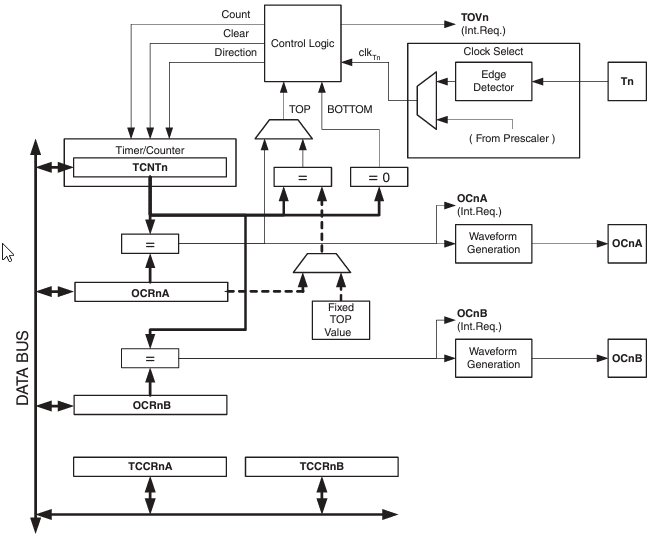
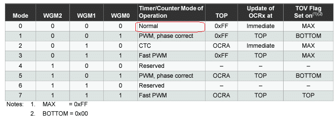
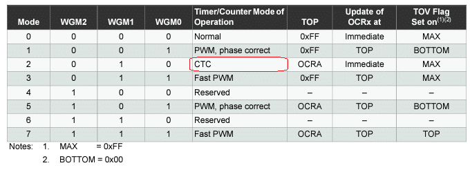
  TCCR0A = 0x00;                  // normal mode counter
 
  TCCR0B = 0x00;
  TCCR0B |= (1<<CS00)|(1<<CS02);  // prescaler set to 1024

  TCNT0 = 0;                      // reset counter

}

void loop() {
  // put your main code here, to run repeatedly:

  if((TIFR &(1 << TOV0)) == 0)  // poll for timer flag
  {
    // do nothing
    
  }else{                        // timer flagged
    
    TIFR |= (1<<TOV0); // reset timer0 flag

    // this is your event
    toggle ^= 1;
    digitalWrite(0, toggle);
  }

}


You may use a timer interrupt to prevent continuous polling of the interrupt flag. However, if you’re using the Arduino IDE, the timer0 overflow interrupt is already used by the milis() function. If you want to use the timer0 overflow interrupt, simply use the routine and program statements below.

				
					// timer0 ovf ISR
ISR(TIMER0_OVF_vect)   
{
  // this is your event
  toggle ^= 1;
  digitalWrite(0, toggle);
}

// enable global interrupt
sei();  

// enable timer ovf interrupt
TIMSK |= (1<<TOIE0); 


USE CASE: Generating a Basic Waveform on a Pin

You can create a basic waveform output through an external pin by utilizing the Waveform Generation Blocks. This requires using the Output Compare registers (OCRx). The output compare registers OCR0A and OCR0B are available for Timer 0.  

The output compare registers act as registers to compare with your timer/counter register. When these registers match, the output compare pin (OCnA or OCnB) may change state depending on what the user wants as long as he activates this feature.

Below, the timer mode operation toggles the output compare pin OC0A on a Compare Match. This process creates a waveform defined by your OCR0A in relation to the changing TCNT value. You may change the OCR0A according to your liking to vary your waveform output.

				
					#include <avr/io.h>

uint8_t toggle;

void setup() {
  // put your setup code here, to run once:
  pinMode(0, OUTPUT);


  TCCR0A = 0x00; // normal mode operation
  TCCR0A |= (1<<COM0A0); // Toggle OC0A on Compare Match


  TCCR0B = 0x00;
  TCCR0B |= (1<<CS00)|(1<<CS02);  // prescaler (1024)  

  OCR0A = 0xFF; // a waveform toggle point

  TCNT0 = 0;

}

void loop() {

}


Note that there is a mode to clear the TCNT value when a compare match occurs. With this, you can create a different kind of waveform (mainly the waveform should have a 50% duty cycle). The counter restarts to zero as it reaches the value of OCR0A. With this process, you can also limit the maximum counter resolution of the timer.

ATTiny85 Timer Mode Clear Timer on Compare Match

Use case: Generating a PWM Waveform

A Pulse Width Modulation waveform can be made that shows up on the output compare pins. You just need to select the proper timer mode operation and output compare pin behavior. Below is an example of one such mode using the Fast PWM Mode. 

ATTiny85 Timer Operation Fast PWM Mode

Here, the Fast PWM mode is chosen along with a clearing of the OC0A pin on a compare match.

				
					#include <avr/io.h>

uint8_t toggle;

void setup() {
  // put your setup code here, to run once:
  pinMode(0, OUTPUT);

  TCCR0A = 0x00; 
  TCCR0A |= (1<<COM0A1);            // Clear OC0A on Compare Match

  TCCR0A |= (1<<WGM01)|(1<<WGM00); // Fast PWM

  TCCR0B = 0x00;
  TCCR0B |= (1<<CS00)|(1<<CS02);  // prescaler (1024)  

  OCR0A = 200;                    // PWM point

  TCNT0 = 0;                      // reset Timer

}

void loop() {


}


Note that the OCR0A register value along with the TCNT running value defines the PWM point on your waveform. By varying the OCR0A value, you can adjust your duty cycle accordingly.

Conclusion

There are different kinds of modes and operations that you can do with a basic ATTiny85 timer. This article just presented a few of them specifically for Timer 0. You can generate events, basic, and PWM waveforms, among others.

SUBSCRIBE FOR NEW POST ALERTS

Subscribe to be the first to know when we publish a new article!
List Subscriptions(Required)

POPULAR POSTS

Scroll to Top