Want to see your KiCAD projects in 3D? Are you ready to house your design in a chassis to make it more secure and presentable? See this article on generating 3D models in KCAD.
Introduction
Last time, you learned to use KiCAD to design and fabricate a PCB. This time, you’ll learn to integrate 3D views into it. As you’ll see, many electronics projects are usually incomplete without a casing or chassis. With this, a 3D model of your PCB design would come in handy. While working with this model, you can verify your board’s orientation and dimensions in relation to your casing. Additionally, rendering 3D models as a part of your documentation makes aesthetically pleasing and professionally made presentations.
As you learn KiCAD, you may go by several 3D rendering options. This article will help you go about these options so that you can successfully render a full PCB design with components in 3D view that is ready to be exported to a 3D CAD software.
Rendering a 3D view of your PCB
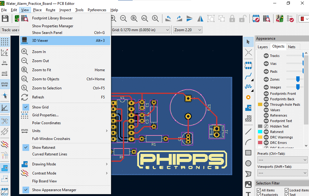
There is an option to instantly render a rotatable 3D view of your entire PCB in KiCAD as was done in the PCB Layout in KiCAD blog. In PCB Editor, simply go to View -> 3D Viewer, or press the shortcut keys Alt+3.
Additionally, this view allows you to hide or show different types of components (such as SMDs, through-holes, or POS file-enabled components) which is useful in documentation. You can also save the entire view as a JPG or PNG file.
HOw the 3D View of your PCB Came About
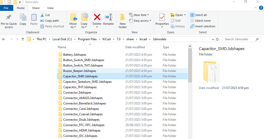
KiCAD can generate the 3D view of your board because individual components have 3D model files inside KiCAD’s 3D model library. Depending on your KiCAD version, you should be able to find this library at:
C:\Program Files\KiCad\7.0\share\kicad\3dmodels
Digging deeper into the directories, you’ll find each component model has two files: namely a WRL and a STEP file. Each kind of file has unique characteristics.
About WRL and STEP files
You may wonder, why KiCAD put in two 3D model files for each component. Isn’t one model file enough? The answer lies in the kind of operation you’ll use the 3D models for.
WRL files
WRL files are Virtual Reality Modeling Language file types. These files don’t clearly define absolute dimensions or units. With these characteristics, they are often used for immersive 3D experiences (such as viewing the 3D PCB model above)
STEP files
Standard for the Exchange of Product model data (or STEP for short), unlike WRL, has clearly defined dimensions, units, and scale. These characteristics make them a perfect choice for exchanging data between different CAD software. Because of this, STEP has become a universal standard for 3D modeling.
The sets of information above can help you choose what type of 3D Model file to use.
Defining The 3D MOdel of each Component to USe
By default, if you have a component coming from the KiCAD library, the 3D model is loaded automatically. However, the default set is a WRL file. If you want to change this or if you have your 3D model to use, you’ll need to enter the component’s properties and then go to the 3D Models tab to choose your 3D model file.
Above, you’ll see U1’s WRL 3D model (a 14-pin DIP IC) was replaced with a STEP file (a 14-pin DIP socket). There are several parameters on the left that you can change if needed. These are the X, Y, and Z scales or offsets. Make sure that your model fits the allocated PCB footprint appropriately.
Exporting Your 3d PCB Model to a CAD Software
To export your 3D PCB Model to CAD software such as FreeCAD (or others), you’ll have to set all the 3D models of each of your components to STEP files. Simply follow the process in the previous topic above. Here, all the components of the board must be set to STEP.
Export your Printed Circuit Board to STEP Format
After setting the model of each component. you can now export your entire PCB to a 3D file. Choose the STEP file format if you want to use a CAD program to view and edit your board. Here, go to File -> Export then Choose the STEP format. Edit certain parameters if required for your model then choose Export.
Open the Generated PCB Step File in your CAD Software
Now that you have generated your PCB 3D Step file, open it on your CAD program. FreeCAD is a good, open-source, and free CAD program that you can use. Simply go to File -> Open and then choose your STEP file. You should see your board along with each component as a part in the 3D Model Viewer.
That’s basically it! You can now create an accurately shaped chassis along with your printed circuit board! 🙂