If you’re finding a way to change the amplitude of your PWM waveform, this article will help you with this task.
Introduction
A PWM (short for Pulse Width Modulation) waveform’s duty cycle or frequency can easily be changed using a microcontroller. It’s most convenient if your device already has a dedicated PWM peripheral to control these parameters. However, it’s uncommon to find MCUs that can vary a PWM’s amplitude in real time. This article presents a unique way of achieving such a feat.
An Example Scenario
Suppose you are slowly blinking some LEDs to a predefined frequency and duty cycle and want to change their brightness or intensity. With this, you already used your MCU’s PWM peripheral and selected the proper frequency and duty cycle parameters. You would have thought the same parameters should adjust the LED’s brightness too. However, you can’t do this anymore since you’ve already used these parameters to set the slow blinking rate.
(A simple example of this application is the Meditation Stimulator fed to a resistor LED combination circuit)
Adding an Analog Switch IC
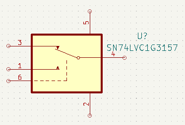
A unique and simple solution without employing a complicated circuit would be to add an analog switch IC. Such IC like the SN74LVC1G3157 from Texas Instruments will do. It’s a Single-Pole Double-Throw Analog Switch, the same as a single-channel analog multiplexer.
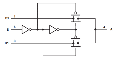
The analog switch will choose between two analog inputs, B1 and B2, through the S (select) pin and output the corresponding waveform to pin A.
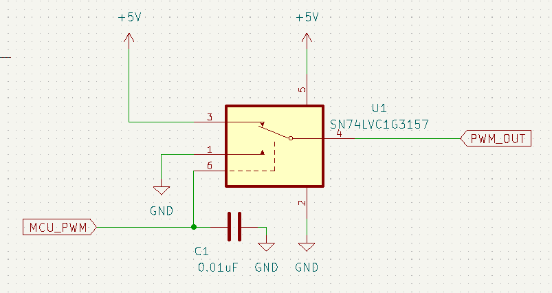
Through this behavior, you can mimic your PWM waveform by connecting your MCU’s PWM pin to the select pin S, connecting B2 to ground and B1 to Vcc. See below. The capacitor was added for good transient stability of the PWM waveform.
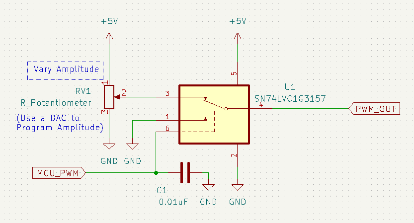
Moreover, to vary the amplitude of your PWM waveform, instead of connecting B1 to Vcc, connect it to a variable voltage reference. The example here uses a potentiometer although you can use something where you can program and vary your PWM’s amplitude such as a DAC.
Circuit in Action
Below is the circuit in action. A resistor LED combination was added to demonstrate the concept visually.