This tutorial will help you program your ESP32 GPIO Ports in VS Code using the ESP-IDF Code Extension.
Introduction
Working with the official ESP-IDF code extension in VS Code unlocks all the features of your ESP32 device. These features include various GPIO port functions. You can find these functions in the APIs or macros of the GPIO Ports library in ESP-IDF.
Before continuing, make sure you’ve read these pre-requisite articles:
Getting Started to Code in ESP-IDF using Visual Studio Code
Run your first esp32 program in Visual Studio Code
How to Create a New Project in ESP-IDF using Visual Studio Code
Here, you’ll learn to initialize your ESP32 I/Os as GPIO through concrete examples.
How do you Initialize the GPIO ports?
First, you should include the peripheral GPIO header file driver/GPIO.h at the beginning of your code. Then, the GPIO ports should be initialized or configured at the start of your program. There are several ways to do this. The easy way is to use the basic GPIO API functions gpio_reset_pin(), gpio_pad_select_gpio(), gpio_set_direction(), and gpio_set_pull_mode(), among others.
There is also another method to configure several GPIOs simultaneously using a data structure. It’s by using gpio_config(). However, you may have to use some bit masking techniques to achieve your desired results. What’s good about gpio_config() is that it automatically sets the pins to the default GPIO state when called.
Below are some practical examples of GPIO configurations in ESP-IDF.
Example 1: Lighting a Multi Color LED Strip
Example 1 shows configuring GPIO ports to light up an LED strip. This example consecutively sets and resets ESP32 pin values. You can refer to the basic circuit of this prototype ESP32 learning Kit for the LED connections.
					#include <stdio.h>
#include "driver\gpio.h"
#include "freeRTOS\freeRTOS.h"
#include "freeRTOS\task.h"

#define LED_STRIP1_G GPIO_NUM_32
#define LED_STRIP1_R GPIO_NUM_33
#define LED_STRIP1_B GPIO_NUM_25

void app_main(void)
{
    // Configure Digital I/O for LEDs

    gpio_set_direction(LED_STRIP1_G, GPIO_MODE_OUTPUT);
    gpio_set_direction(LED_STRIP1_R, GPIO_MODE_OUTPUT);
    gpio_set_direction(LED_STRIP1_B, GPIO_MODE_OUTPUT);

    while(1)
    {

    // LED STRIP 1
        gpio_set_level(LED_STRIP1_G, 1);
        vTaskDelay(100);
        gpio_set_level(LED_STRIP1_G, 0);

        gpio_set_level(LED_STRIP1_R, 1);
        vTaskDelay(100);
        gpio_set_level(LED_STRIP1_R, 0);

        gpio_set_level(LED_STRIP1_B, 1);
        vTaskDelay(100);
        gpio_set_level(LED_STRIP1_B, 0);
        vTaskDelay(100);

    }


}
At the beginning of the code, several definitions exist to map the GPIO pins correctly. In main, gpio_set_direction(pin number, gpio mode) sets the gpios as outputs. After that, gpio_set_level(pin number, level) outputs the desired logic of the pin inside a while loop with delays.
Seeing the code execution above, you’ll notice some uninitialized ports having their LED strip lit up. You should be able to correct this by adding gpio_pad_select_gpio() to these ports to get them to a gpio state.
Example 2: Another Method to Configure the GPIO ports
Example 2 initializes and configures the GPIOs using the gpio_config() API. Three LED strips are used here, and the ports are configured through one gpio_config() statement. Note that there are several other statements required before executing the said API. A gpio_config_t structure should be filled with values beforehand.
					#include <stdio.h>
#include "driver\gpio.h"
#include "freeRTOS\freeRTOS.h"
#include "freeRTOS\task.h"

#define LED_STRIP1_G GPIO_NUM_32
#define LED_STRIP1_R GPIO_NUM_33
#define LED_STRIP1_B GPIO_NUM_25

#define LED_STRIP2_G GPIO_NUM_26
#define LED_STRIP2_R GPIO_NUM_27
#define LED_STRIP2_B GPIO_NUM_2

#define LED_STRIP3_G GPIO_NUM_13
#define LED_STRIP3_R GPIO_NUM_14
#define LED_STRIP3_B GPIO_NUM_15

#define LED_STRIP1_BIT_MASK (1ULL << LED_STRIP1_G | 1ULL << LED_STRIP1_R | 1ULL << LED_STRIP1_B)
#define LED_STRIP2_BIT_MASK (1ULL << LED_STRIP2_G | 1ULL << LED_STRIP2_R | 1ULL << LED_STRIP2_B)
#define LED_STRIP3_BIT_MASK (1ULL << LED_STRIP3_G | 1ULL << LED_STRIP3_R | 1ULL << LED_STRIP3_B)


gpio_config_t myGPIOconfig;

void app_main(void)
{
    // Configure Digital I/O for LEDs
    myGPIOconfig.pin_bit_mask = (LED_STRIP1_BIT_MASK | LED_STRIP2_BIT_MASK | LED_STRIP3_BIT_MASK);
    myGPIOconfig.pull_down_en = GPIO_PULLDOWN_DISABLE;
    myGPIOconfig.pull_up_en = GPIO_PULLUP_DISABLE;
    myGPIOconfig.mode = GPIO_MODE_OUTPUT;
    myGPIOconfig.intr_type = GPIO_INTR_DISABLE;

    gpio_config(&myGPIOconfig);


    while(1)
    {

    // LED STRIP 1
        gpio_set_level(LED_STRIP1_G, 1);
        vTaskDelay(100);
        gpio_set_level(LED_STRIP1_G, 0);

        gpio_set_level(LED_STRIP1_R, 1);
        vTaskDelay(100);
        gpio_set_level(LED_STRIP1_R, 0);

        gpio_set_level(LED_STRIP1_B, 1);
        vTaskDelay(100);
        gpio_set_level(LED_STRIP1_B, 0);
        vTaskDelay(100);

    // LED STRIP 2
        gpio_set_level(LED_STRIP2_G, 1);
        vTaskDelay(100);
        gpio_set_level(LED_STRIP2_G, 0);

        gpio_set_level(LED_STRIP2_R, 1);
        vTaskDelay(100);
        gpio_set_level(LED_STRIP2_R, 0);

        gpio_set_level(LED_STRIP2_B, 1);
        vTaskDelay(100);
        gpio_set_level(LED_STRIP2_B, 0);
        vTaskDelay(100);

    // LED STRIP 3
        gpio_set_level(LED_STRIP3_G, 1);
        vTaskDelay(100);
        gpio_set_level(LED_STRIP3_G, 0);

        gpio_set_level(LED_STRIP3_R, 1);
        vTaskDelay(100);
        gpio_set_level(LED_STRIP3_R, 0);

        gpio_set_level(LED_STRIP3_B, 1);
        vTaskDelay(100);
        gpio_set_level(LED_STRIP3_B, 0);
        vTaskDelay(100);

    }


}
Bit mask, pull down, pull up, mode, and interrupt properties are the required fields to be filled up in the structure. Several bit masks can be OR’ed together to represent the different GPIO ports.
As in the previous example, the LEDs are lighted consecutively with delays.
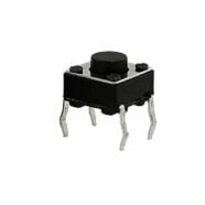
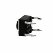
Example 3: Push Buttons as Inputs
Example 3 configures GPIOs as inputs to get the digital values of several push-button switches so that the user can control the lights of an LED strip. An internal pull-up resistor is also enabled in one of those ports. The other ports are pulled up through external resistors because they don’t have internal pull-ups.
					#include <stdio.h>
#include "driver\gpio.h"
#include "freeRTOS\freeRTOS.h"
#include "freeRTOS\task.h"

#define LED_STRIP1_G GPIO_NUM_32
#define LED_STRIP1_R GPIO_NUM_33
#define LED_STRIP1_B GPIO_NUM_25

#define LED_STRIP2_G GPIO_NUM_26
#define LED_STRIP2_R GPIO_NUM_27
#define LED_STRIP2_B GPIO_NUM_2

#define LED_STRIP3_G GPIO_NUM_13
#define LED_STRIP3_R GPIO_NUM_14
#define LED_STRIP3_B GPIO_NUM_15

#define LED_STRIP1_BIT_MASK (1ULL << LED_STRIP1_G | 1ULL << LED_STRIP1_R | 1ULL << LED_STRIP1_B)
#define LED_STRIP2_BIT_MASK (1ULL << LED_STRIP2_G | 1ULL << LED_STRIP2_R | 1ULL << LED_STRIP2_B)
#define LED_STRIP3_BIT_MASK (1ULL << LED_STRIP3_G | 1ULL << LED_STRIP3_R | 1ULL << LED_STRIP3_B)

#define PUSH_BUTTON_1 GPIO_NUM_4
#define PUSH_BUTTON_2 GPIO_NUM_35
#define PUSH_BUTTON_3 GPIO_NUM_36

#define PUSH_BUTTON_1_BIT_MASK (1ULL << PUSH_BUTTON_1)
#define PUSH_BUTTON_2_BIT_MASK (1ULL << PUSH_BUTTON_2)
#define PUSH_BUTTON_3_BIT_MASK (1ULL << PUSH_BUTTON_3)


gpio_config_t myGPIOconfig;

void app_main(void)
{
    // Configure Digital I/O for LEDs
    myGPIOconfig.pin_bit_mask = (LED_STRIP1_BIT_MASK | LED_STRIP2_BIT_MASK | LED_STRIP3_BIT_MASK);
    myGPIOconfig.pull_down_en = GPIO_PULLDOWN_DISABLE;
    myGPIOconfig.pull_up_en = GPIO_PULLUP_DISABLE;
    myGPIOconfig.mode = GPIO_MODE_OUTPUT;
    myGPIOconfig.intr_type = GPIO_INTR_DISABLE;

    gpio_config(&myGPIOconfig);

    myGPIOconfig.pin_bit_mask = (PUSH_BUTTON_2_BIT_MASK | PUSH_BUTTON_3_BIT_MASK);
    myGPIOconfig.pull_down_en = GPIO_PULLDOWN_DISABLE;
    myGPIOconfig.pull_up_en = GPIO_PULLUP_DISABLE;
    myGPIOconfig.mode = GPIO_MODE_INPUT;
    myGPIOconfig.intr_type = GPIO_INTR_DISABLE;

    gpio_config(&myGPIOconfig);

    gpio_set_direction(PUSH_BUTTON_1, GPIO_MODE_INPUT);
    gpio_set_pull_mode(PUSH_BUTTON_1, GPIO_PULLUP_ONLY);


    while(1)
    {

    // LED STRIP 1
    if(gpio_get_level(PUSH_BUTTON_1) == 0) {
        gpio_set_level(LED_STRIP1_G, 1);
        vTaskDelay(100);
        gpio_set_level(LED_STRIP1_G, 0);

        gpio_set_level(LED_STRIP1_R, 1);
        vTaskDelay(100);
        gpio_set_level(LED_STRIP1_R, 0);

        gpio_set_level(LED_STRIP1_B, 1);
        vTaskDelay(100);
        gpio_set_level(LED_STRIP1_B, 0);
        vTaskDelay(100);
    }

    // LED STRIP 2
    if(gpio_get_level(PUSH_BUTTON_2) == 0) {
        gpio_set_level(LED_STRIP2_G, 1);
        vTaskDelay(100);
        gpio_set_level(LED_STRIP2_G, 0);

        gpio_set_level(LED_STRIP2_R, 1);
        vTaskDelay(100);
        gpio_set_level(LED_STRIP2_R, 0);

        gpio_set_level(LED_STRIP2_B, 1);
        vTaskDelay(100);
        gpio_set_level(LED_STRIP2_B, 0);
        vTaskDelay(100);
    }

    // LED STRIP 3
    if(gpio_get_level(PUSH_BUTTON_3) == 0) {
        gpio_set_level(LED_STRIP3_G, 1);
        vTaskDelay(100);
        gpio_set_level(LED_STRIP3_G, 0);

        gpio_set_level(LED_STRIP3_R, 1);
        vTaskDelay(100);
        gpio_set_level(LED_STRIP3_R, 0);

        gpio_set_level(LED_STRIP3_B, 1);
        vTaskDelay(100);
        gpio_set_level(LED_STRIP3_B, 0);
        vTaskDelay(100);

    }

    }

}
The ports can be configured as input GPIOs with pull-ups through the mode and pull_up_en structure members of the gpio_config_t. Alternatively, they can be configured using the gpio_set_direction() and gpio_set_pull_mode() statements.
Example 4: Open Drain Outputs
Example 4 configures one GPIO as an output in open drain configuration. You can drive external components with a higher supply voltage in this configuration. You can take out one transistor driver of a port and then hook the pin directly to the LED strip. This setup is okay as long as you drive the port in open drain. Note, however, that it has an inverted logic because it’s open-drain. After writing the other gpio initialization statements, issue the gpio_set_direction(LED_STRIP1_G, GPIO_MODE_OUTPUT_OD) statement to set a pin as open drain.