Would you like to learn to program an ESP32? Don’t know where to start? Building your own ESP32 learning kit will accelerate and ease your learning curve. See below to find out.
Introduction
A learning kit is a fun way to learn about electronics. Most beginners can benefit from purchasing such a kit. However, if you’re on a tight budget and have spare off-the-shelf components available, it wouldn’t hurt to build one yourself. Here, you’ll learn to assemble a simple learning kit for your ESP32 Devkit modules.
With this kit, you’ll be able to learn simple tasks such as lighting an LED or detecting button presses. You’ll also learn sophisticated tasks such as acquiring sensor data, running an OLED screen, or observing RTOS thread behaviors through buttons, LED indicators and a display device.
RGB LED indicators, transistors, tact switches, a DHT11 sensor module, a 10k Potentiometer, and an OLED Serial Display make up the primary components of this kit. Additionally, get an ESP32 Devkit module that has accessible pins.
3 pcs. RGB LED strip (min strip)
3 pcs. 3-pin header connectors
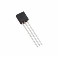
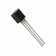
9 pcs. 2N3904 or 2N2222 or equivalent
9 pcs. 4.7k ohm 0.25W resistors
3 pcs. tactile buttons
1 pc. Breadboard
Solid connecting wires
1 pc. DHT11 Temp Sensor Module
1 pc. 128xOLED Serial Display Module
1 pc. ESP32 DevKit
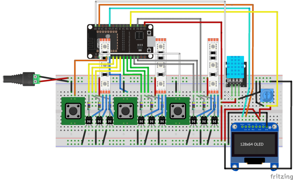
Wire the Components and Connect them to your ESP32 Devkit
The wiring below is for a 30-pin ESP32 Devkit V1 module. However, with some modifications, you may adapt this to a Wemos LOLIN D32 or even the Huzzah32 and ESP32-S2 Feather Boards. Whichever unit you have, what’s important is proper connection to your ports that has digital or special-purpose functions. The table below will guide you accordingly.
Custom ESP32 Learning Kit Connections
ESP32 PIN
Function
Component
LEDSTRIP GPIO PORTS
D32
GPIO OUT
RGB LED STRIP 1
D33
GPIO OUT
RGB LED STRIP 1
D25
GPIO OUT
RGB LED STRIP 1
D26
GPIO OUT
RGB LED STRIP 2
D27
GPIO OUT
RGB LED STRIP 2
D14
GPIO OUT
RGB LED STRIP 2
D12
GPIO OUT
RGB LED STRIP 3
D13
GPIO OUT
RGB LED STRIP 3
D15
GPIO OUT
RGB LED STRIP 3
BUTTONS PORTS
D34
GPIO IN
TACT SW1
D35
GPIO IN
TACT SW2
D36/VP
GPIO IN
TACT SW3
POTENTIONMETER PORT
D4
ADC2_0 IN
POTENTIOMETER
TEMP/HUMIDITY SENSOR PORT
D23
GPIO OUT/IN
DGT11 MODULE
OLED PORTS
D22
I2C-SCL
128x64 OLED
D21
I2C-SDA
128x64 OLED
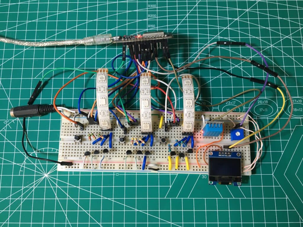
Here is an actual snapshot for prototype of the breadboarded learning kit.
In the future, you should be able to make your own PCB with this learning kit module.