If you are curious about the workings of a device driver, read the article to learn more about its implementation and practice.
Introduction
During the early programming days, your microcontroller’s devices or peripherals (such as an ADC, UART, SPI, or Timer) can straightforwardly be controlled through register manipulation. However, now, different development environments (most notably, the Arduino IDE) eliminate the necessity of directly accessing such registers; they already provide a simpler, more convenient way of doing this through their rich set of user-friendly APIs.
These APIs came about all thanks to techniques learned from software layering. One particular layer, the Hardware Abstraction Layer, has helped developers implement microcontroller peripherals in a more generalized and easy-to-understand way. This implementation method allows compatibility on different chip series and versions and configuration in an ordered manner.
As microcontrollers became more powerful, they embraced operating systems concepts (like FreeRTOS). With this, additional methods are implemented to take control of your device. The Device drivers and the other substantial layers (HAL, RTOS/OS, etc.) take care of this process. These layers provide developers ease of programming sophisticated microcontroller devices.
The Hardware Abstraction Model
The reason for the ease of access of your devices or peripherals from your application while maintaining efficiency, performance, and portability is through a Hardware Abstraction Layout. An example of such a layout found in popular development environments is:
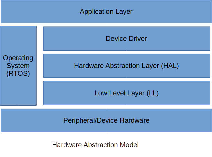
- LL or Lower Level Layer
- HAL or Hardware Abstraction Layer
- Device Driver Layer
Lower Level Layer (LL)
The Lower Level Layer comprises functions and macros directly acting on the peripheral/device registers. LL has the lowest level of access to these registers. With this, they are optimized for speed and code size. LL directly interacts with the HAL layer.
Hardware Abstraction Layer (HAL)
HAL has added benefits over LL because it’s made for portability and ease of configuration/implementation. You’ll see that you can use HAL to configure a wide range of your chipset series. The HAL functions/macros also have a detailed sequence of steps to configure your device. After that, it also has detailed steps to operate your device.
Device Driver Layer
Device drivers manage your peripherals/devices as they are used by an operating system such as RTOS. An Operating System usually has multiple processes or tasks in the background as you operate your device. Additionally, different tasks might access your devices at the same time. With this, you should have a Device driver to handle such things.
Example Device Driver Application
Uart Driver in ESP-IDF
Here is a typical application of a UART Driver in ESP-IDF using their example code. Here, you’ll see three parts, all using the Hardware Abstraction Model previously discussed:
- UART peripheral and pin configuration (LL and HAL)
- UART driver installation (Device Driver Layer)
- UART operation through RTOS tasks (Application Layer)
					/* UART asynchronous example, that uses separate RX and TX tasks

   This example code is in the Public Domain (or CC0 licensed, at your option.)

   Unless required by applicable law or agreed to in writing, this
   software is distributed on an "AS IS" BASIS, WITHOUT WARRANTIES OR
   CONDITIONS OF ANY KIND, either express or implied.
*/
#include "freertos/FreeRTOS.h"
#include "freertos/task.h"
#include "esp_system.h"
#include "esp_log.h"
#include "driver/uart.h"
#include "string.h"
#include "driver/gpio.h"

static const int RX_BUF_SIZE = 1024;

#define TXD_PIN (GPIO_NUM_4)
#define RXD_PIN (GPIO_NUM_5)

void init(void) {
    const uart_config_t uart_config = {
        .baud_rate = 115200,
        .data_bits = UART_DATA_8_BITS,
        .parity = UART_PARITY_DISABLE,
        .stop_bits = UART_STOP_BITS_1,
        .flow_ctrl = UART_HW_FLOWCTRL_DISABLE,
        .source_clk = UART_SCLK_DEFAULT,
    };
    // We won't use a buffer for sending data.
    uart_driver_install(UART_NUM_1, RX_BUF_SIZE * 2, 0, 0, NULL, 0);
    uart_param_config(UART_NUM_1, &uart_config);
    uart_set_pin(UART_NUM_1, TXD_PIN, RXD_PIN, UART_PIN_NO_CHANGE, UART_PIN_NO_CHANGE);
}

int sendData(const char* logName, const char* data)
{
    const int len = strlen(data);
    const int txBytes = uart_write_bytes(UART_NUM_1, data, len);
    ESP_LOGI(logName, "Wrote %d bytes", txBytes);
    return txBytes;
}

static void tx_task(void *arg)
{
    static const char *TX_TASK_TAG = "TX_TASK";
    esp_log_level_set(TX_TASK_TAG, ESP_LOG_INFO);
    while (1) {
        sendData(TX_TASK_TAG, "Hello world");
        vTaskDelay(2000 / portTICK_PERIOD_MS);
    }
}

static void rx_task(void *arg)
{
    static const char *RX_TASK_TAG = "RX_TASK";
    esp_log_level_set(RX_TASK_TAG, ESP_LOG_INFO);
    uint8_t* data = (uint8_t*) malloc(RX_BUF_SIZE+1);
    while (1) {
        const int rxBytes = uart_read_bytes(UART_NUM_1, data, RX_BUF_SIZE, 1000 / portTICK_PERIOD_MS);
        if (rxBytes > 0) {
            data[rxBytes] = 0;
            ESP_LOGI(RX_TASK_TAG, "Read %d bytes: '%s'", rxBytes, data);
            ESP_LOG_BUFFER_HEXDUMP(RX_TASK_TAG, data, rxBytes, ESP_LOG_INFO);
        }
    }
    free(data);
}

void app_main(void)
{
    init();
    xTaskCreate(rx_task, "uart_rx_task", 1024*2, NULL, configMAX_PRIORITIES, NULL);
    xTaskCreate(tx_task, "uart_tx_task", 1024*2, NULL, configMAX_PRIORITIES-1, NULL);
}
The init( ) function configures as well as installs the UART driver.
Inside the init( ) function, the peripheral configuration is seperate and can be broken down further into two functions, namely uart_param_config( ) and uart_set_pin( ). Looking closely at uart_param_config( ), you’ll see several HAL functions.
					esp_err_t uart_param_config(uart_port_t uart_num, const uart_config_t *uart_config)
{
    ESP_RETURN_ON_FALSE((uart_num < UART_NUM_MAX), ESP_FAIL, UART_TAG, "uart_num error");
    ESP_RETURN_ON_FALSE((uart_config), ESP_FAIL, UART_TAG, "param null");
    ESP_RETURN_ON_FALSE((uart_config->rx_flow_ctrl_thresh < SOC_UART_FIFO_LEN), ESP_FAIL, UART_TAG, "rx flow thresh error");
    ESP_RETURN_ON_FALSE((uart_config->flow_ctrl < UART_HW_FLOWCTRL_MAX), ESP_FAIL, UART_TAG, "hw_flowctrl mode error");
    ESP_RETURN_ON_FALSE((uart_config->data_bits < UART_DATA_BITS_MAX), ESP_FAIL, UART_TAG, "data bit error");
    uart_module_enable(uart_num);
#if SOC_UART_SUPPORT_RTC_CLK
    if (uart_config->source_clk == UART_SCLK_RTC) {
        periph_rtc_dig_clk8m_enable();
    }
#endif
    uint32_t sclk_freq;
    ESP_RETURN_ON_ERROR(uart_get_sclk_freq(uart_config->source_clk, &sclk_freq), UART_TAG, "Invalid src_clk");

    UART_ENTER_CRITICAL(&(uart_context[uart_num].spinlock));
    uart_hal_init(&(uart_context[uart_num].hal), uart_num);
    uart_hal_set_sclk(&(uart_context[uart_num].hal), uart_config->source_clk);
    uart_hal_set_baudrate(&(uart_context[uart_num].hal), uart_config->baud_rate, sclk_freq);
    uart_hal_set_parity(&(uart_context[uart_num].hal), uart_config->parity);
    uart_hal_set_data_bit_num(&(uart_context[uart_num].hal), uart_config->data_bits);
    uart_hal_set_stop_bits(&(uart_context[uart_num].hal), uart_config->stop_bits);
    uart_hal_set_tx_idle_num(&(uart_context[uart_num].hal), UART_TX_IDLE_NUM_DEFAULT);
    uart_hal_set_hw_flow_ctrl(&(uart_context[uart_num].hal), uart_config->flow_ctrl, uart_config->rx_flow_ctrl_thresh);
    UART_EXIT_CRITICAL(&(uart_context[uart_num].spinlock));
    uart_hal_rxfifo_rst(&(uart_context[uart_num].hal));
    uart_hal_txfifo_rst(&(uart_context[uart_num].hal));
    return ESP_OK;
}
If you now go inside one of the HAL functions (like uart_hal_init( )), you’ll see several Low Level (LL) functions which reiterates the Hardware Abstraction model.
					void uart_hal_init(uart_hal_context_t *hal, int uart_num)
{
    // Set default clock source
    uart_ll_set_sclk(hal->dev, UART_SCLK_DEFAULT);
    // Set UART mode.
    uart_ll_set_mode(hal->dev, UART_MODE_UART);
    // Disable UART parity
    uart_ll_set_parity(hal->dev, UART_PARITY_DISABLE);
    // 8-bit world
    uart_ll_set_data_bit_num(hal->dev, UART_DATA_8_BITS);
    // 1-bit stop bit
    uart_ll_set_stop_bits(hal->dev, UART_STOP_BITS_1);
    // Set tx idle
    uart_ll_set_tx_idle_num(hal->dev, 0);
    // Disable hw-flow control
    uart_ll_set_hw_flow_ctrl(hal->dev, UART_HW_FLOWCTRL_DISABLE, 100);
}
The UART device driver installation is also in a separate unit in uart_driver_install( ). Looking closely at the prototype of this function:
Install UART driver and set the UART to the default configuration. UART ISR handler will be attached to the same CPU core that this function is running on.
Parameters:uart_num – UART port number, the max port number is (UART_NUM_MAX -1).rx_buffer_size – UART RX ring buffer size.tx_buffer_size – UART TX ring buffer size. If set to zero, driver will not use TX buffer, TX function will block task until all data have been sent out.queue_size – UART event queue size/depth.uart_queue – UART event queue handle (out param). On success, a new queue handle is written here to provide access to UART events. If set to NULL, driver will not use an event queue.intr_alloc_flags – Flags used to allocate the interrupt. One or multiple (ORred) ESP_INTR_FLAG_* values. See esp_intr_alloc.h for more info. Do not set ESP_INTR_FLAG_IRAM here (the driver’s ISR handler is not located in IRAM)
Returns:
- ESP_OK Success – ESP_FAIL Parameter error
Note:
Rx_buffer_size should be greater than UART_FIFO_LEN. Tx_buffer_size should be either zero or greater than UART_FIFO_LEN.
You’ll see some RTOS related primitives (like queue size and uart_queue) included in the parameters, indicating the uart_driver_install( ) function is essential for the UART peripheral to work correctly with the operating system.
Finally, you’ll get to operate your UART peripheral in a thread-safe manner by creating user-defined transmit or receive tasks in main:
					void app_main(void)
{
    init();
    xTaskCreate(rx_task, "uart_rx_task", 1024*2, NULL, configMAX_PRIORITIES, NULL);
    xTaskCreate(tx_task, "uart_tx_task", 1024*2, NULL, configMAX_PRIORITIES-1, NULL);
}
These tasks are defined by these functions:
					int sendData(const char* logName, const char* data)
{
    const int len = strlen(data);
    const int txBytes = uart_write_bytes(UART_NUM_1, data, len);
    ESP_LOGI(logName, "Wrote %d bytes", txBytes);
    return txBytes;
}

static void tx_task(void *arg)
{
    static const char *TX_TASK_TAG = "TX_TASK";
    esp_log_level_set(TX_TASK_TAG, ESP_LOG_INFO);
    while (1) {
        sendData(TX_TASK_TAG, "Hello world");
        vTaskDelay(2000 / portTICK_PERIOD_MS);
    }
}

static void rx_task(void *arg)
{
    static const char *RX_TASK_TAG = "RX_TASK";
    esp_log_level_set(RX_TASK_TAG, ESP_LOG_INFO);
    uint8_t* data = (uint8_t*) malloc(RX_BUF_SIZE+1);
    while (1) {
        const int rxBytes = uart_read_bytes(UART_NUM_1, data, RX_BUF_SIZE, 1000 / portTICK_PERIOD_MS);
        if (rxBytes > 0) {
            data[rxBytes] = 0;
            ESP_LOGI(RX_TASK_TAG, "Read %d bytes: '%s'", rxBytes, data);
            ESP_LOG_BUFFER_HEXDUMP(RX_TASK_TAG, data, rxBytes, ESP_LOG_INFO);
        }
    }
    free(data);
}
TaskS Demo
In case you have a stack overflow, please increase the stack size of the uart_rx_task( ).