Need to find a GPIO pin on the ESP32-S3 DevKitC-1? Want to learn how to configure it? Read this ESP32-S3 DevkitC-1 pinouts guide.
Introduction
The ESP32-S3 DevKitC-1 is the latest development kit from Espressif that uses its flagship ESP32 device. Once you get a new devkit, you get excited to test its functions. However, as any electronic hobbyist knows, the test usually starts with a Blinky Project.
Here, you’ll get to know more than just creating a Blinky Project for your ESP32-S3 DevKitC-1. You get one step further by knowing all the available GPIO ports for the user. With this, you won’t find yourself scratching your head asking why one GPIO port doesn’t work.
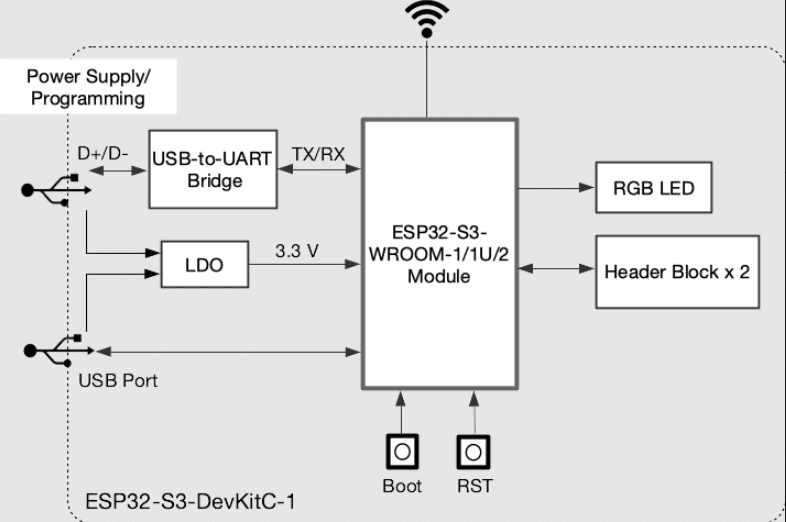
The ESP32-S3 DevKitC-1 Block Diagram
To start off, here is the basic block diagram of the ESP32-S3 Devkit-C1.
As you can see, the devkit has a USB-to-UART converter module, an LDO, a USB Port, an RGB LED, a Boot and Reset pin, and two Header blocks, besides the main chip ESP32-S3-WROOM.
The ESP32-S3 DevKitC-1 GPIO Pins
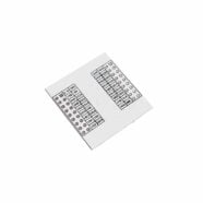
Here are the available GPIO pins on the headers of your ESP32-S3 Devkit. Note that they are color-coded according to priority or optional functions. The entries are further explained in the next sections. However, as you’ll see later, not every GPIO pin functions out of the box as a GPIO Port.
ESP32-S3 DevKitC-1 GPIO Pinouts (Left Header)
Pin Number
Marking
Function
1
3V3
3.3V
2
3V3
3.3V
3
RST
Reset Pin
4
4
GPIO4
5
5
GPIO5
6
6
GPIO6
7
7
GPIO7
8
15
GPIO15
9
16
GPIO16
10
17
GPIO17
11
18
GPIO18
12
8
GPIO8
13
3
GPIO3
14
46
GPIO46
15
9
GPIO9
16
10
GPIO10
17
11
GPIO11
18
12
GPIO12
19
13
GPIO13
20
14
GPIO14
21
5Vin
5V Supply from USB-C
22
GND
Ground
ESP32-S3 DevKitC-1 GPIO Pinouts (Right Header)
Pin Number
Marking
Function
23
GND
Ground
24
GND
Ground
25
19
GPIO19
26
20
GPIO20
27
21
GPIO21
28
47
GPIO47
29
48
GPIO48
30
45
GPIO45
31
0
GPIO0
32
35
GPIO35
33
36
GPIO36
34
37
GPIO37
35
38
GPIO38
36
39
GPIO39
37
40
GPIO40
38
41
GPIO41
39
42
GPIO42
40
2
GPIO2
41
1
GPIO1
42
RX
GPIO44
43
TX
GPIO43
44
GND
Ground
First Priority GPIO Ports
The first priority GPIO ports are the ones that can be used as GPIO ports after a system boot. These ports are already available at this point, no special setup is required. They are colored green on the header pins table.
GPIO1
GPIO2
GPIO4
GPIO5
GPIO6
GPIO7
GPIO8
GPIO9
GPIO10
GPIO11
GPIO12
GPIO13
GPIO14
GPIO15
GPIO16
GPIO17
GPIO18
GPIO21
GPIO38
GPIO47
GPIO48
With these ports, you just need to set up the GPIO mode to your liking and then proceed with your intended operation. See Working with ESP32 GPIO Ports in ESP-IDF to view more examples of this kind.
					    // Set as GPIO input or output
    gpio_set_direction(GPIO_NUM_1, GPIO_MODE_OUTPUT);
    gpio_set_direction(GPIO_NUM_2, GPIO_MODE_INPUT);
    gpio_set_direction(GPIO_NUM_4, GPIO_MODE_OUTPUT_OD);
					// use the GPIO
gpio_set_level(GPIO_NUM_1, 1);
gpio_set_level(GPIO_NUM_4, 0);

if(gpio_get_level(GPIO_NUM_2) == 0)
{
    // some statement
};
Second Priority GPIO Ports
The second priority GPIO pins have other functions that may affect a particular system or behavior. With this, you have to pay special attention if using them as GPIO affects that behavior. Here are those pins including the extra functions they have.
GPIO0 – Boot Strapping Pin Boot Mode
GPIO3 – Boot Strapping Pin JTAG
GPIO19 – USB
GPIO20 – USB
GPIO39 – JTAG/MTCK
GPIO40 – JTAG/MTDO
GPIO41 – JTAG/MTDI
GPIO42 – JTAG/MTMS
GPIO43 – UART0 TX/Debug
GPIO44 – UART0 RX/Debug
GPIO45 – Boot Strapping Pin VDD SPI Voltage
GPIO46 – Boot Strapping Pin Boot Mode / ROM Messages
Some of these pins might not get set to GPIO by default during bootup. With this, you have to explicitly state to have them set as GPIO. You can do this like what the example statements below do. You can check Working with ESP32 GPIO Ports in ESP-IDF for working examples.
					// declare a gpio_config_t variable
gpio_config_t myGPIOconfig;

// configure the GPIO port
gpio_config(&myGPIOconfig);
					// use the gpio_pad_select() function
esp_rom_gpio_pad_select_gpio(GPIO_NUM);
Optional GPIO Ports
These Optional GPIO ports can be used as long as they are not purposed for Octal SPI Flash or PSRAM functions. This really depends on the model of your ESP32-S3 DevKitC-1. Some models, especially the higher-end WROOM models, may use these pins as extra SPI communication pins for the Flash/PSRAM modules. It’s recommended to check your device datasheet.