Working with digital audio can be a challenge in the beginning. Have a primer on the I2S standard to fully understand what this serial audio protocol does.
Introduction
Analog audio had its days in the past. When designing such a system, you must be careful of some critical layout rules. You had to ensure you had a separate ground path for the analog returns. It would be best if you also shielded the audio paths so as not to pick up stray noise from the surroundings.
As digital audio picked up its phase, more and more designs utilized digital audio serial protocols. This is mainly to avoid the pitfalls of analog hardware and design. With this, a popular serial protocol called I2S or Inter-Integrated Sound bus is utilized by many high-tech audio devices today. In addition to this, many of these audio devices usually have other digital tech-related applications such as wireless streaming, communications, and digital signal processing.
The I2S Standard
Its Inception and Basic Workings
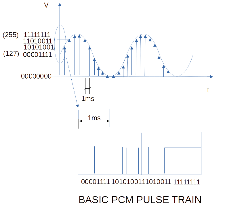
Philips developed I2S in the ’80s. It uses a popular digitizing technique called PCM (or Pulse Coded Modulation) to represent its sampled analog data. PCM, in itself, is uncompressed data. You see PCM used in popular digital formats such as CDs and DVDs. This format is also used in computer audio and digital communications.
The figure below illustrates a crude basic 8-bit 1kHz PCM sampling technique together with its pulse train.
The I2S Lines
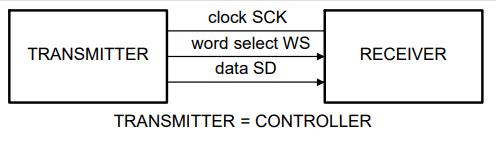
I2S does a lot of digital sampling and outputs quantized digital data in PCM form. With this, comes a digital clock line, as well as serial data out. Additionally, I2S uses a chanell select line that allows channel selection (like left and right channels). This means no additional lines are needed to output separate channels. This group of data comprises the standard I2S wires BCLK/SCK (for clock), SDO/SD (for serial data out), and WS (or Word Select, which selects between channels). Below is a diagram of the I2S wires according to the Philips I2S Specification document
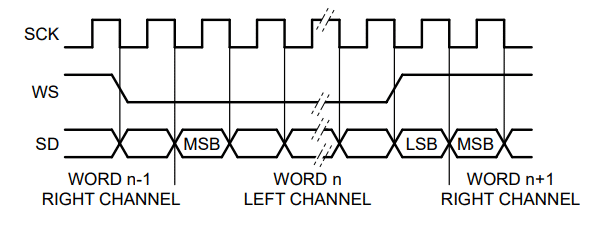
Below is a diagram of the I2S waveforms.
How Does The I2S Protocol Work
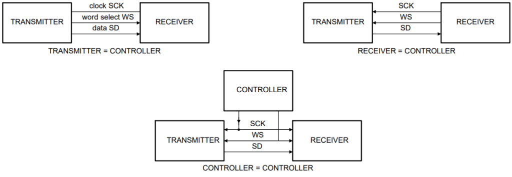
I2S data can both be transmitted and received. It implements a master-slave relationship on its transmitter and receiver side. The master can be the transmitter or receiver of the I2S serial data and is usually called the controller. The slave can also be in transmitter or receiver mode. However, once communication is established, this relationship cannot be changed. Below is a diagram of different I2S master-slave configurations.
The controller outputs the bit clock and word select line. The serial data can be from the controller or receiver side depending on the user’s configuration. A remote configurator, other than the master or slave, can also be incorporated into your setup.
Conclusion and Future Works
You’ve just learned about the basic fundamentals of the I2S standard. You are now ready to implement it in hardware and firmware. Stay tuned for future posts about implementing I2S on your favorite development boards or development kits.