Introduction
Interrupt Service Routines(or ISRs) are integral to microcontroller operation. Knowing how to use them correctly can not only improve the efficiency of your programs but also avoid potential pitfalls in code. Here, you’ll learn about Interrupt Service Routine best practices.
What IS an Interrupt Service Routine
An ISR is a chunk of code that executes when an Interrupt from a peripheral or MCU event happens. This routine is given an address in your code and is jumped at during the interrupt event through a lookup table called an Interrupt Vector Table (IVT).
The lookup table’s addresses have space between each entry enough to contain data to know where to jump to your ISR address. The IVT gets referred during an IRQ (Interrupt Request) from a peripheral or MCU interrupt event. During an IRQ event, main program execution is halted to give way to the execution of code in the interrupt routine. After your ISR finishes, the main program continues its execution from where it left off.
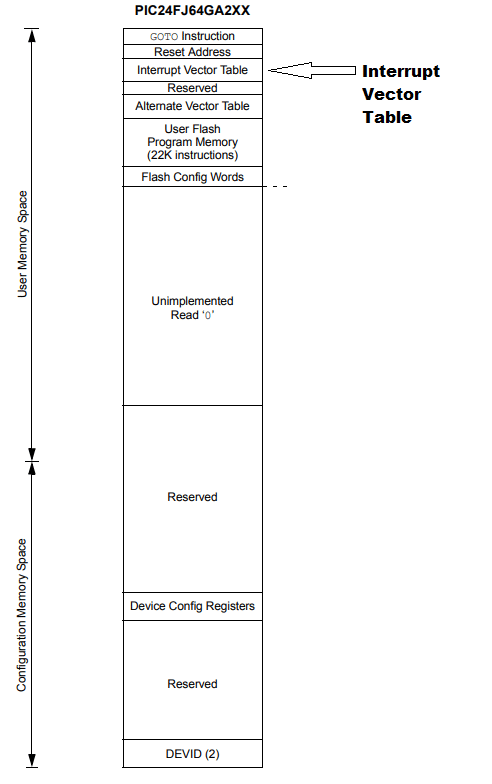
Below is an example of where the IVT resides in program memory, for a known microcontroller, and the entries inside it.
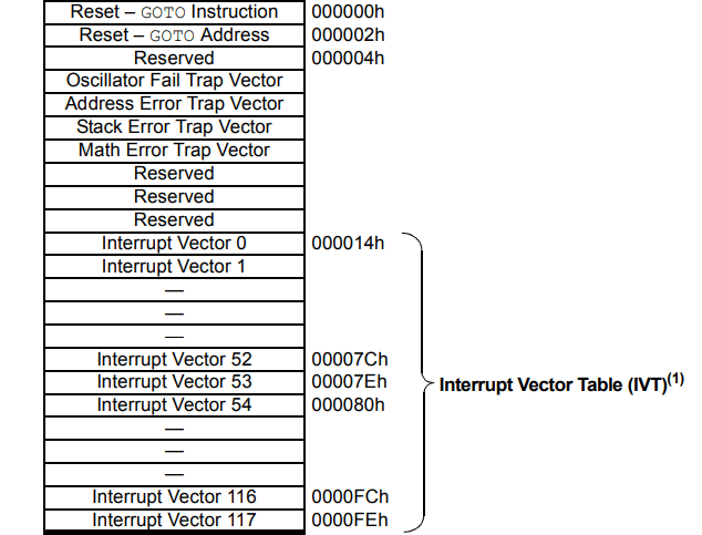
Below is an example of IVT entries and their corresponding addresses.
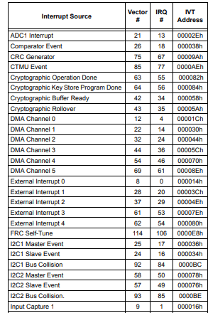
Below again are the interrupt sources together with their corresponding vector number, IVT address, and IRQ.
Good ISR Practices to Consider
As was said earlier, an interrupt interrupts normal program execution. With this, you have to be wary of how you write your Interrupt Service Routine so that it will have minimal effect on the flow of your program. Below are some Interrupt Service Routine best practices
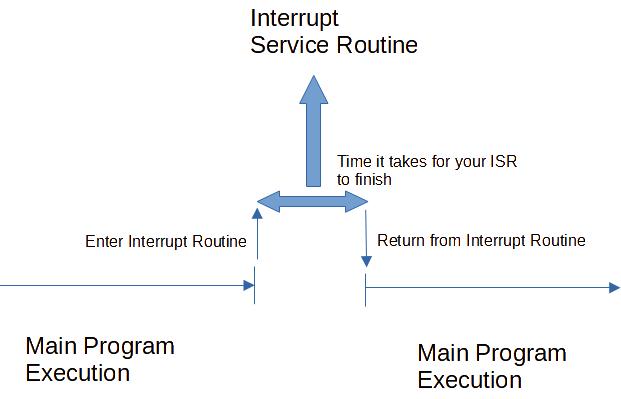
- Try to make your ISR code as short as possible. Remember that ISRs will take over normal program execution. You want this moment to be as short as possible not to disrupt your program flow. For example, it wouldn’t be good to see your ISR code messing up a timing requirement or adding distraction to a smooth-running GUI. Note that normal program execution continues as you exit your ISR routine.
- Instead of bombarding your ISR with code, you can alternately introduce a global variable, such as a flag. This flag can be set on your ISR when an interrupt happens to let your main program know. You can acknowledge this event in main and structure your program to respond in a way suitable for your application. The example code in the next part will illustrate this.
- The variable flags you used and the same variables or registers you access/modify in your ISR or main should be accessed in one atomic operation. An atomic operation is an instruction executed in one read or write cycle. Since ISR disrupts normal program execution, it can happen that a single operation with multiple read or write cycles can be disrupted. All the while, you are also accessing this same data in your ISR or main. If this happens, you may end up with garbled data.
A Good Example of an ISR Routine
The code below assumes you have a basic understanding of STM32 Cube IDE and the BluePill. If not you can browse STM32 Cube IDE Tutorial
About the Code
Below is code that has a requirement where your program prints UART messages only every 500ms. The UART message timing is made through a timer resource T2 that interrupts every 500ms. To keep the code efficient and organized, a timer flag variable, timer_flag is used to signal to main, from the T2_ISR, that the timer event happened. The timer_flag is of type int to ensure atomic operation if it is accessed by both main and the T2 ISR. Additionally, the volatile qualifier is used for the flag to ensure the compiler does not optimize things out.
Next, there is also code that lets your main program know if a single UART data is available on the same port. This is possible through the flag mechanism again. The UART_ISR contains a uart_rx_flag that is polled in main. The main code prints a message on the console that it received such data. However, note that the timing of printing the event of a received UART message coincides with the 500ms period of timer T2 which is the primary requirement of this program.
The Interrupt Flags
The declaration of the flags is at the top part of main. If your interrupt code (ISR) is in another file, it’s necessary to use the extern qualifier. Otherwise, this can be omitted.
					/* USER CODE BEGIN PV */

extern int volatile timer_flag;
extern int volatile uart_rx_flag;
/* USER CODE END PV */
Start the Interrupt based Peripherals
Next, both the interrupt-based timer and the receive UART function are started.
					  /* USER CODE BEGIN 2 */
  HAL_TIM_Base_Start_IT(&htim2);

  uint8_t buff;
  HAL_UART_Receive_IT(&huart1, &buff, 1);

  /* USER CODE END 2 */
The Main Loop
The main loop is seen below. Note that the timer flag is polled. The uart rx flag is also polled, but inside the condition when the timer flag is activated (hence, keeping true the 500ms UART print requirement). There is no issue in this case because of the flag mechanism in your ISRs as you’ll see later. The flags keep the state of the interrupts as well as keep the ISR routines short.
					  /* Infinite loop */
  /* USER CODE BEGIN WHILE */
  while (1)
  {
	  if(timer_flag)
	  {
		  timer_flag = 0;
		  HAL_GPIO_TogglePin(LED_GPIO_Port, LED_Pin);

		  if(uart_rx_flag)
		  {
			  // Transmit UART data
			  HAL_UART_Transmit(&huart1, (uint8_t*)("UART Received a Packet\r\n"), 24, 10);
			  uart_rx_flag = 0;

			  // re-enable UART receive mode
			  HAL_UART_Receive_IT(&huart1, &buff, 1);

		  }else{
			  // Transmit UART data
			  HAL_UART_Transmit(&huart1, (uint8_t*)"UART is Working\r\n", 16, 10);
		  }

	  }
    /* USER CODE END WHILE */

    /* USER CODE BEGIN 3 */

  }
  /* USER CODE END 3 */
}
The ISR Structure
Next, we go to the ISR structure. If your ISR is in a separate file, you should also declare your flags there.
					/* USER CODE BEGIN PV */
int volatile timer_flag;
int volatile uart_rx_flag;
/* USER CODE END PV */
Here are your Interrupt Service Routines for both the timer and the receive interrupt. Note that there is only one user statement inside the routines. The lone statement simply activates the flag for the peripheral when their interrupt happens.
					/******************************************************************************/
/* STM32F1xx Peripheral Interrupt Handlers                                    */
/* Add here the Interrupt Handlers for the used peripherals.                  */
/* For the available peripheral interrupt handler names,                      */
/* please refer to the startup file (startup_stm32f1xx.s).                    */
/******************************************************************************/

/**
  * @brief This function handles TIM2 global interrupt.
  */
void TIM2_IRQHandler(void)
{
  /* USER CODE BEGIN TIM2_IRQn 0 */

	timer_flag = 1;

  /* USER CODE END TIM2_IRQn 0 */
  HAL_TIM_IRQHandler(&htim2);
  /* USER CODE BEGIN TIM2_IRQn 1 */

  /* USER CODE END TIM2_IRQn 1 */
}

/**
  * @brief This function handles USART1 global interrupt.
  */
void USART1_IRQHandler(void)
{
  /* USER CODE BEGIN USART1_IRQn 0 */

	uart_rx_flag = 1;

  /* USER CODE END USART1_IRQn 0 */
  HAL_UART_IRQHandler(&huart1);
  /* USER CODE BEGIN USART1_IRQn 1 */

  /* USER CODE END USART1_IRQn 1 */
}
demo
The demo above shows how this code with the two ISRs has minimal lag and timing issues with each other, satisfying the program requirement.
Conclusion
You’ve just learned how to create efficient and reliable Interrupt Service Routines by following best practices.
SHOP THIS PROJECT
-
Digital LCD Thermometer Temperature Gauge with Probe
$15.95Original price was: $15.95.$14.95Current price is: $14.95. Add to cart

