Have you tried to program using STM32CubeIDE? Want a tutorial and a guide on how to use it? Read through the article to find out.
Introduction
ST Microelectronics has created their own IDE for programming their STM32 microcontroller devices. This is called STM32CubeIDE. This IDE integrates several ST software components that will make debugging and programming of your ST devices much easier.
What do you need to program with STM32CubeIDE?
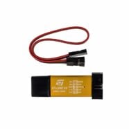
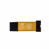
You simply need to download STM32CubeIDE from ST’s website and have an ST-Link hardware programmer/debugger. The downloaded software installation package automatically installs and updates the necessary packages for you. With this, you’re up and ready to start your STM32CubeIDE tutorial.
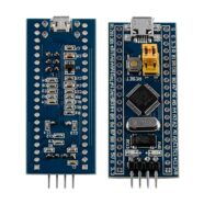
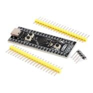
Start Programming with STM32 Cube IDE using a BluePill
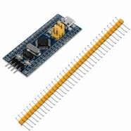
Although a BluePill can be programmed using the Arduino environment, using official tools from ST makes things a lot easier. See the process below:
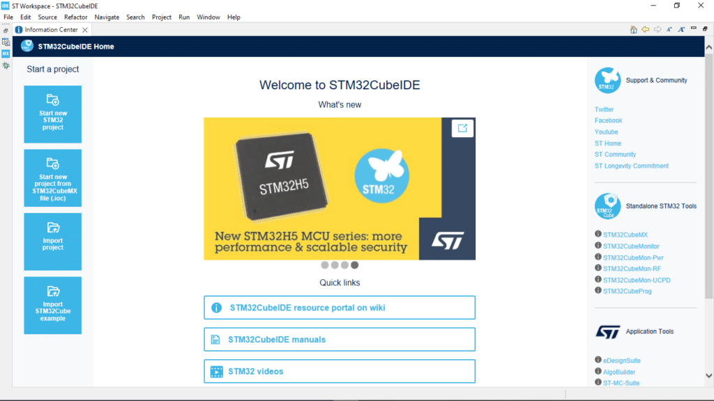
Open STM32Cube IDE and see the welcome screen.
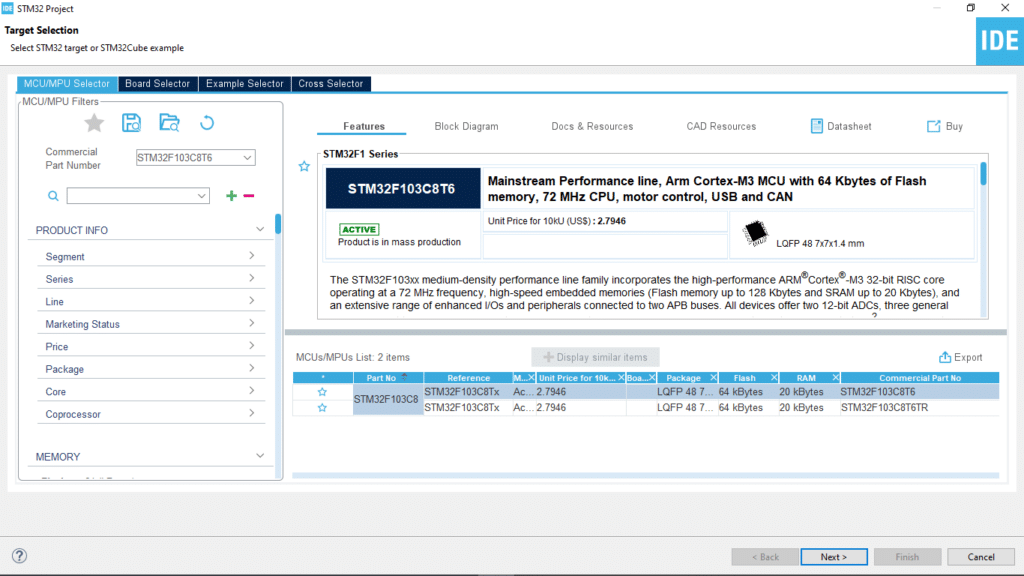
Pick Start new STM32 project on the left. You’ll be shown a target selector to pick your STM32 chip or development board. Click Next to continue.
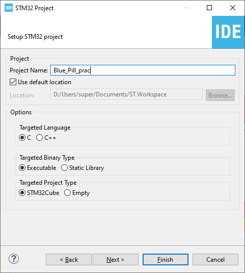
You’ll be asked to input a project name next. For starters, choose the default parameters and then click Finish.
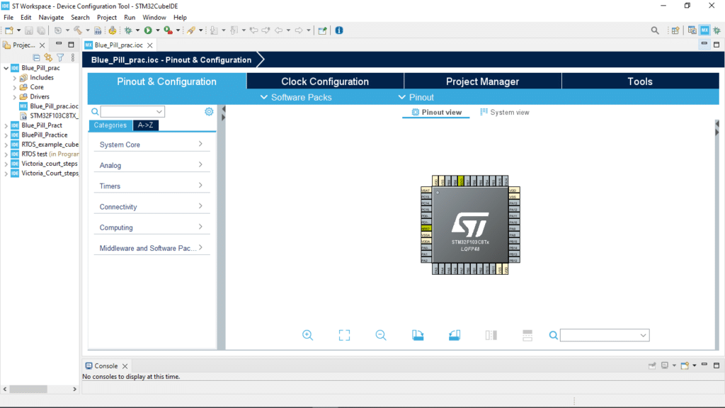
The process will continue to the STM32 CubeMX graphical interface. This is were you can easily assign pins and various functions to your chip.
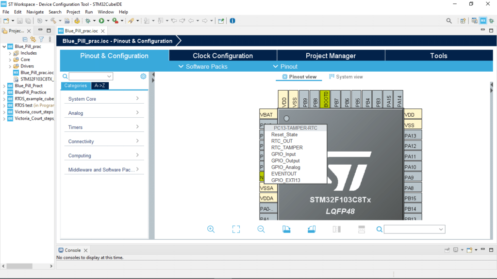
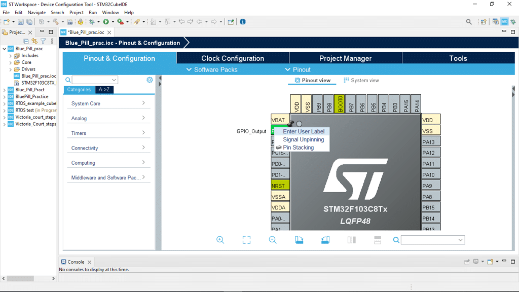
Let’s assign an LED port. Since PC13 is where the builtin LED of the BluePill is, let’s assign it here. You’ll have to left click on the pin and then set it as GPIO Output. To label the pin, right click on it then click on Enter User Label.
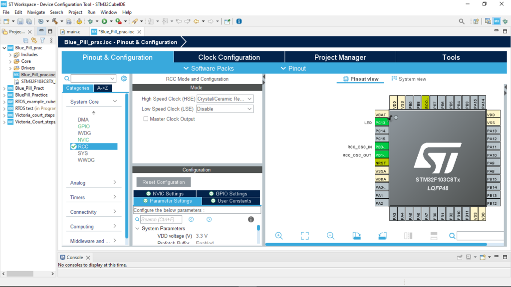
One more thing, you have to select a proper clock source for your chip to work. With this, go to the System Core -> RCC and select Crystal Ceramic Resonator as High Speed Clock Source.
Now go to the Clock Configuration tab to establish your system clock. There is an auto configuration tool here so watch the video below on how to set a maximum system clock rate of 72 MHz.
After this, you can proceed to generate a C code that you can edit by saving your STM32CubeMX IOC data. With this, click the save icon on the upper left, and then proceed to the programming editor perspective view.
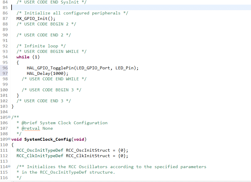
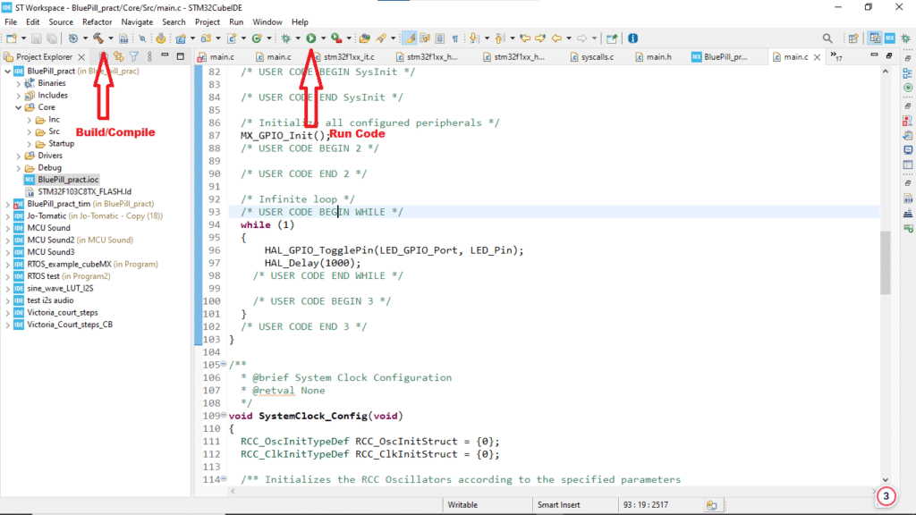
You will be able to see your project on the left pane in programming editing perspective. Go to Core -> Src folder to view your main.c file. You’ll see that there are commented USER CODE areas where you can do your edits. It’s not recommended to edit the other parts since CubeMX can replace them if it regenerates code. In your main in the main loop, try to toggle the LED port using the HAL_GPIO_Toggle( ) function. Toggle the LED with a 1 second delay with the HAL_Delay( ) function as seen below.
					  /* Infinite loop */
  /* USER CODE BEGIN WHILE */
  while (1)
  {
	  HAL_GPIO_TogglePin(LED_GPIO_Port, LED_Pin);
	  HAL_Delay(1000);
    /* USER CODE END WHILE */

    /* USER CODE BEGIN 3 */
  }
  /* USER CODE END 3 */
}
You can begin compiling the code by clicking the Build button. You can program the board by clicking the Run button. With this, make sure you’ve attached your ST-Link to your BluePill and PC.
Hope you’ve learned a lot on this STM32CubeIDE tutorial!