void dispUART(void *argument)
{
/* USER CODE BEGIN UARTmenu */
/* Infinite loop */
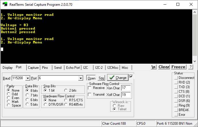
Menu_Display();
for(;;)
{
// select user input
if (HAL_UART_Receive(&huart1, &choice, sizeof(choice), 10) == HAL_OK)
{
switch (choice) {
case '1':
//HAL_UART_Transmit(&huart1, (uint8_t*)"2 pressed\r\n", sizeof("1 pressed\r\n"), 10);
sprintf(buffer, "Voltage = %d\r\n",x_val);
HAL_UART_Transmit(&huart1, buffer, sizeof(buffer), 10);
break;
case '2':
Menu_Display();
break;
default:
break;
}
}else{
}
if(button1_pressed)
{
HAL_UART_Transmit(&huart1, (uint8_t*)"Button1 pressed\r\n", sizeof("Button1 pressed\r\n"), 10);
button1_pressed = 0;
}
if(button2_pressed)
{
HAL_UART_Transmit(&huart1, (uint8_t*)"Button2 pressed\r\n", sizeof("Button2 pressed\r\n"), 10);
button2_pressed = 0;
}
osDelay(100);
}
/* USER CODE END UARTmenu */
}