Introduction
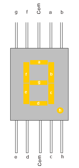
Seven segment displays have a total of 10 pins (including VCC and GND). In order to display something on a 7-segment display using an Arduino, approximately 7 digital I/O pins would be required. Because of this, it would be more practical to use shift registers to drive 7-segment displays.

The Arduino UNO has 14 digital I/O pins in total. Therefore using the majority of the pins for the 7-segment display is inefficient. If you think about it, you can utilize these pins for other functions. The use of Shift Registers and the Shift Register library can overcome such issues.
Project
Equipment Needed
- Arduino Uno
- External 5V Power Supply
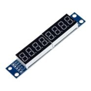
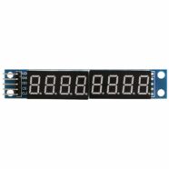
- 7 segment display – 2 pieces
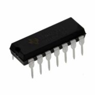
- Shift Registers – 2 pieces
- 680 ohms resistors – 14 pieces
- Breadboard
- Connecting wires
Shift Registers
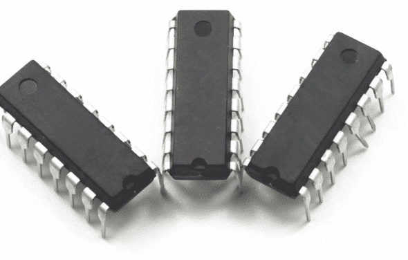
Shift Registers are sequential logic circuits that can be used to store and transfer binary data. These components store data in registers that are moved or “shifted” to the required bit-positions on each clock pulse. The registers are loaded with serial data, one bit at a time, with the stored data made available at the output pins in parallel form.
Please refer to the following tutorials for additional information:
Shift Register 74HC595 Library
This library simplifies shift register usage. For example, the libraries’ functions can be used to set shift register pins just like normal Arduino pins (e.g. sr.set(1, HIGH)).
If you want to know more about the shift register library, its author Tim Denk explains this well.
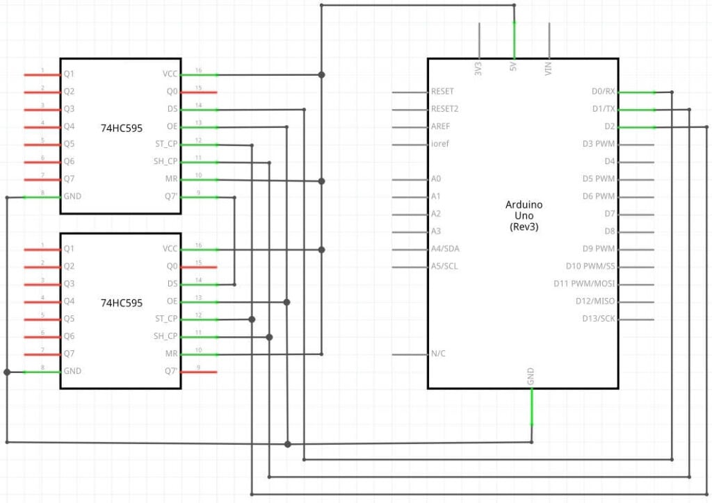
Schematic Diagram
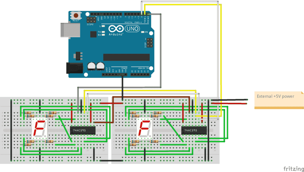
These are the connections for two 7-segment displays driven by shift registers on an Arduino UNO. The wiring looks complicated because some of them overlap each other. However, it’s important to ensure the pins connected to the Arduino from the Shift registers and the pins from the seven segments to the shift registers are properly connected as shown from the recommendation of Tim Denk in the diagram below.
Connection Explanation
Pin numbers Q0 to Q6 of the shift registers should be connected sequentially to the LCD display pins (A-G).
For example:
- The Q0 pin of the Shift register connects to Pin-A of the display.
- The Q1 pin of the Shift register connects to Pin-B of the display.
- The Q2 pin of the Shift register connects to Pin-C of the display.
- and so on…
You’ll be able to relate these pin assignments to entries in the num_array[10] array in the code later.
The ST-CP and SH-CP are the storage register and shift register clock pins of the shift registers. The Shift register library will take care of the functions of these pins. They are connected to digital pins D2 and D1 of the Arduino.
The DS or Serial Data Input pin of the first shift register is directly connected to Arduino’s D0 digital pin. This outputs serial data in line with the shift register clock. Meanwhile, the Q7′ output of the first shift register is connected in series to the DS pin of the second shift register. This makes cascading possible.
The use of an external power source is recommended to power the Shift Registers and LEDs. Connect the VCC of the Shift Register with an external power source and ensure the ground of that power source is common to all.
The Code
					#include <ShiftRegister74HC595.h>

uint8_t num_array[10] = { B00111111,    // 0
                          B00000110,    // 1
                          B01011011,    // 2
                          B01001111,    // 3
                          B01100110,    // 4
                          B01101101,    // 5
                          B01111101,    // 6
                          B00000111,    // 7
                          B01111111,    // 8
                          B01100111 };  // 9

// create shift register object (number of shift registers, data pin, clock pin, latch pin)
ShiftRegister74HC595 sr (2, 0, 1, 2);

void setup() {
}

void loop() {

  uint8_t pinValues[2] = { B00000000, B00000000 };

  for (int i = 0; i < 100; i++) {
  int x = i/10;
  int y = i-(x*10);

  pinValues[0] = num_array[y];
  pinValues[1] = num_array[x];

  sr.setAll(pinValues);
  delay(100);
  }

}
Code Explanation
The ShiftRegister74HC595 sr (2, 0, 1, 2) statement states that a ShiftRegister74HC595 object is being created. The first argument is the number of Shift Registers to be used. Any number of shift registers can be used based on your project. These shift registers can be controlled easily using the library.
Below is a program that counts from 0 to 99 while displaying the numbers on the 7-segment LED display. The Num_array array of variables holds the seven segments’ LED assignments with respect to the displayed numbers.
The for-loop inside the loop function counts from the numbers 0 to 99. The 2 numerals in the count are broken down into 2-digit numbers by a mathematical operation on the variable i. The numbers appear on display after executing the sr.setAll( ) function from the Shift Register library.
This example can be extended to enable any number of Shift Registers to be used with 7-segments displays.
SHOP THIS PROJECT
-
Sale!

UNO R3 ATmega328P CH340 Development Board – Arduino Compatible with USB Cable
$23.95Original price was: $23.95.$22.95Current price is: $22.95. Add to cart