Would you like to set up a low-cost power supply for your workbench? Want to learn power supply fundamentals with it? Read the rest of the article to find out more.
Introduction
A power supply is basic equipment for any electronics workbench. You’ll always need this to power up your circuits or prototypes. If you build one, make sure you know the fundamentals that go with it. Otherwise, you might end up with a power supply that’s not up to your specification.
In this article, you’ll learn about the different stages involved in a basic linear power supply. You’ll learn each of their function along with example circuits. You can use this as a mini resource to create your power supply. Consequently, browse through our parts list in our store to find different kinds of power supply parts.
Parts / Stages of a Basic Linear Power Supply
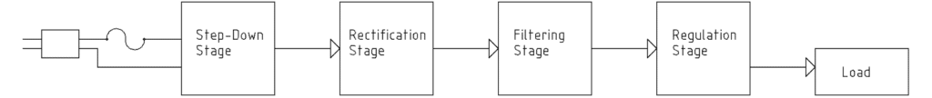
Step-Down Stage
If you’re sourcing power from your mains, a step-down converter stage is necessary. This will ensure your mains 110V/220V is stepped down just enough to be used by your power supply circuit. Without it, it’s almost impossible to work on the source supply because it’s too high. This will require a more expensive components bill-of-materials you’ll want to avoid.
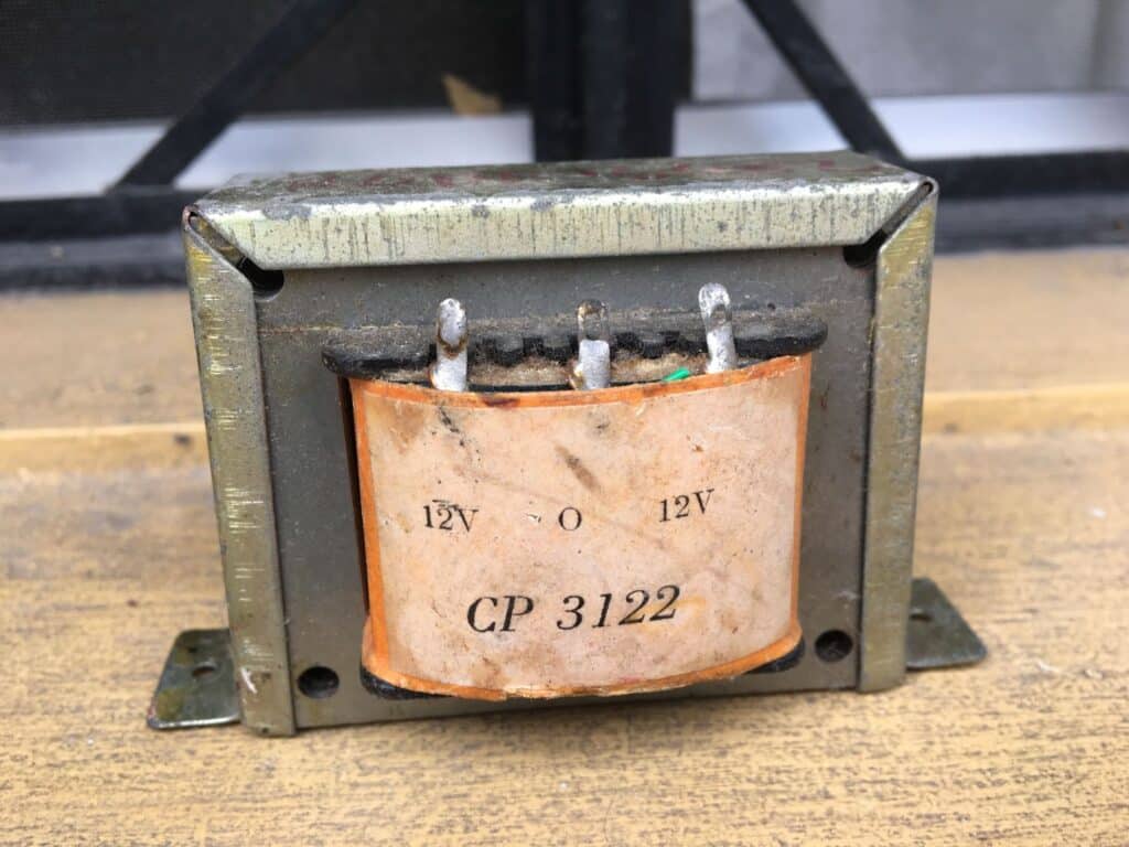
The step-down converter is usually a transformer. You can find this at your local electronics shop. Depending on the power rating of your power supply, transformers can get a bit bulky. However, they provide sound isolation from your mains.
The transformer has both a primary and a secondary winding, and they are effectively isolated from one another. Your mains are usually connected to the primary winding, and one of your mains terminals is connected or has a return path to earth ground. By employing isolation, you avoid being electrocuted through a current path from your mains.
The transformer’s secondary winding connects to your power supply circuit. It can be connected on two ends, centre-tapped or multi-tapped, depending on your transformer type and your rectifier circuit that will be discussed next.
Rectification Stage
Because the output of the secondary winding of your transformer is AC (Alternating Current), it must be transformed into a DC (Direct Current) type (at least a pulsating DC) so that it can be used for DC circuits. A rectification stage is necessary. This stage is composed of rectifier diodes. Below are some examples of rectifier diodes.
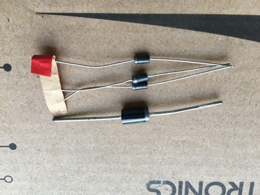
The diode’s size is usually in proportion to the current capacity it can handle. Common rectifier diodes are the 1N4001 to 1N4007 series and the 1N5401 – 1N5408 series. 1N400X’s are designed to handle about an ampere of current, while the 1N540x’s are for 3.0 amps. The number at the end of their names signifies the amount of reverse voltage they can handle. Below is an example of information extracted from a datasheet for the 1N400X and 1N540x series.
| PARAMETER | SYMBOL | 1N4001 | 1N4002 | 1N4003 | 1N4004 | 1N4005 | 1N4006 | 1N4007 | UNIT |
|---|---|---|---|---|---|---|---|---|---|
| Maximum repetitive peak reverse voltage | VRRM | 50 | 100 | 200 | 400 | 600 | 800 | 1000 | V |
| Maximum RMS voltage | VRMS | 35 | 70 | 140 | 280 | 420 | 560 | 700 | V |
| Maximum DC blocking voltage | VDC | 50 | 100 | 200 | 400 | 600 | 800 | 1000 | V |
| Maximum average forward rectified current 0.375" (9.5mm) lead length at TA = 75 °C | IF(AV) | 1.0 | A | ||||||
| MAXIMUM RATINGS (TA = 25 °C Unless otherwise noted) | |||||||||
| PARAMETER | SYMBOL | 1N5400 | 1N5401 | 1N5402 | 1N5403 | 1N5404 | 1N5405 | 1N5406 | 1N5407 | 1N5408 | UNIT |
|---|---|---|---|---|---|---|---|---|---|---|---|
| Maximum repetitive peak reverse voltage | VRRM | 50 | 100 | 200 | 300 | 400 | 500 | 600 | 800 | 1000 | V |
| Maximum RMS voltage | VRMS | 35 | 70 | 140 | 210 | 280 | 350 | 420 | 560 | 700 | V |
| Maximum DC blocking voltage | VDC | 50 | 100 | 200 | 300 | 400 | 500 | 600 | 800 | 1000 | V |
| Maximum average forward rectified current 0.5" (12.5mm) lead length at TL = 105 °C | IF(AV) | 1.0 | A | ||||||||
| MAXIMUM RATINGS (TA = 25 °C unless otherwise noted) | |||||||||||
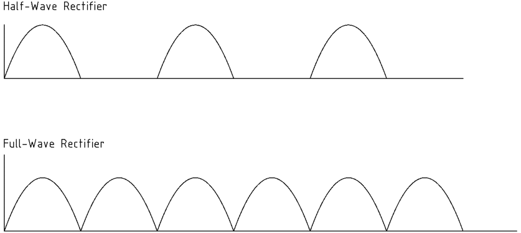
These diodes may be connected to create a full-wave or a half-wave rectifier. Full-wave rectifiers create full-wave pulsating DC waveforms. Half-wave rectifiers create half-wave pulsating DC waveforms, as seen below.
There are different topologies in using a rectifier circuit. This also depends on your transformer type. Center-tapped transformers require fewer diodes to create full-wave waveforms. Transformers with two terminals on their secondary windings may need a bridge-type rectifier composed of four diodes to create full-wave waveforms. To create half-wave waveforms, just a single diode can be used.
Here are several examples of rectifier circuits:
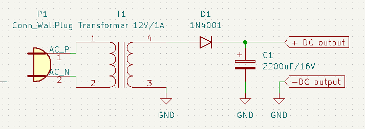
An example of a half-wave rectifier
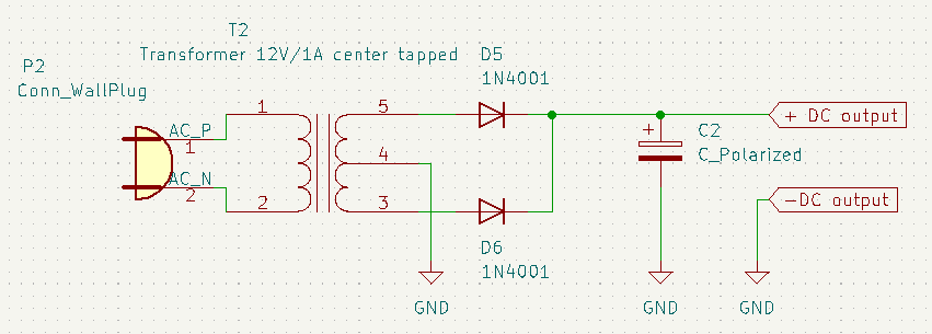
An example full-wave rectifier using a centre-tapped transformer
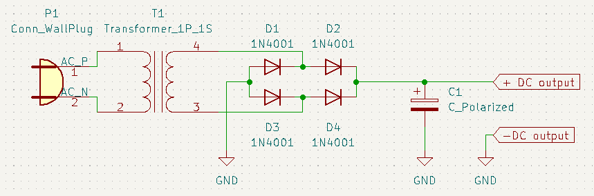
An example of a full-wave bridge-type rectifier using a regular two-terminal transformer.
Filtering Stage
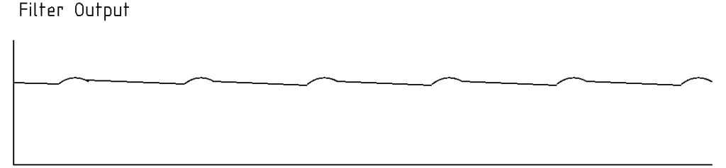
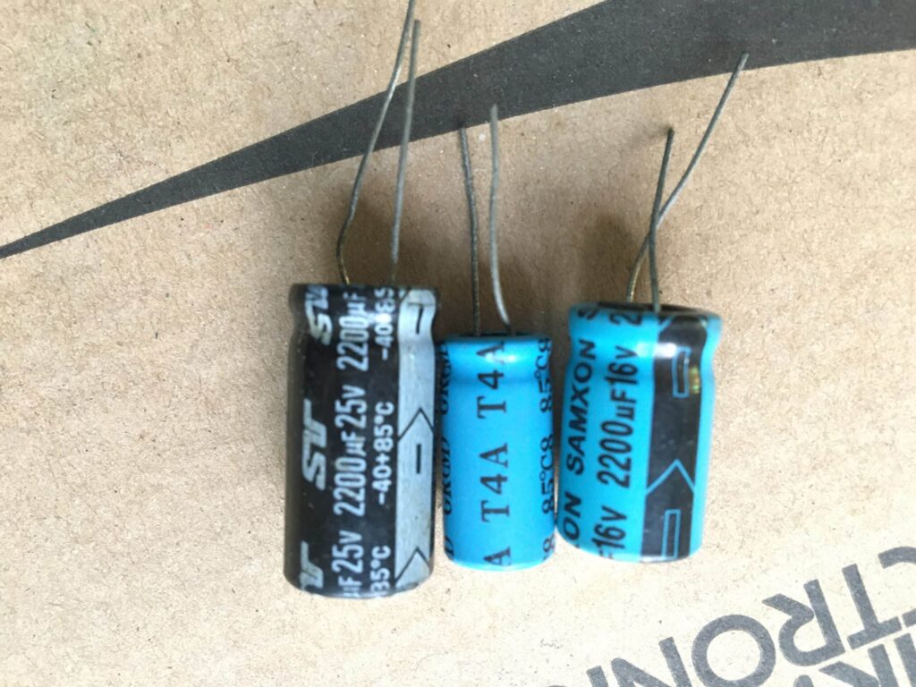
After the rectification stage, a filtering stage comes next. This smoothens out the pulsating DC output creating an almost perfect DC waveform. The component used here is a capacitor. The capacitor charges during the pulsating DC waveforms but does not fully discharge. This effectively creates a waveform with lesser ripple as can be seen below:
You’ll have to use bulk capacitors as a power supply filter. This is due to the slow frequency of the mains at 50 or 60 HZ. It’s ideal to use a large capacitor value (typically 1000uf – 2200uf and above) as your power supply increases in current capacity. The larger the value, the longer it can hold its charge while supplying power to your load.
Regulation Stage
The regulation stage comprises discrete or integrated circuit semiconductors and passives. This stage tries to maintain a constant output voltage to deliver the right amount of current to your load. This stage also smoothens any ripples left from the filter stage. Typically, a voltage regulator is employed here. An example of a voltage regulator is a simple transistor-Zener diode combination, as seen in the figure.
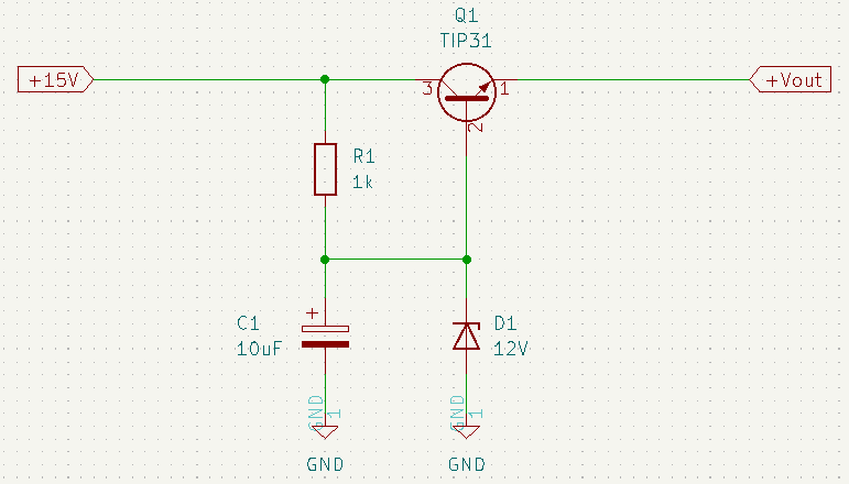
Here a constant voltage is generated across the Zener diode D1 through the current path from the +15V source and resistor R1. C1 stabilises this constant voltage from any fluctuations coming from the source power supply. Transistor Q1 serves as a pass transistor to supply enough current to the load. The total voltage on the output is the Zener diode voltage minus the Vbe drop (0.7v) on the base-emitter junction of the transistor.
A more frequently used type of voltage regulator is the 78XX series. It’s a 3-terminal integrated circuit that’s specialized for this purpose. It incorporates current limit, short circuit, and thermal protection features. The IC is available in many fixed voltage values, such as 12V for 7812, 9V for 7909, 5V for 7805, and others. It can supply about 1.5 amps of current (max). A variable IC voltage regulator can also be used, such as the LM317.
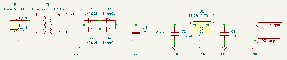
Here is a complete circuit for a 12V/1A regulated power supply. The voltage regulator used is a 7812. Note that there are two smaller capacitors after the bulk filter capacitor C1. They were added for the stability of the 7812. C2 is needed for input stability, while C3 is for output stability.
Conclusion
A basic linear power supply consists of a step-down, rectifier, filter, and regulator stage. Each of these stages was explained. Different transformers, rectifiers, filters, and regulators were also explored. Several circuits were made to illustrate the workings of a linear power supply. Upon reading this article, you should be able to create a basic linear power supply to power your circuits and prototypes.


