Are you having issues with your I2C Arduino codes? Do you want to do some low-level debugging on it? This article will help you by discussing in-depth I2C concepts.
Introduction
I2C (or Inter-integrated circuit) is a serial protocol that’s been in the electronics world for several decades. It has proved its robustness and effectiveness in delivering reliable serial communication between different devices. Its primary purpose is for inter-chip communication between a master and a slave device.
In this article, we’ll discuss basic I2C concepts and the standard protocol and give practical applications so you can exercise the concepts on your own. Once you familiarise yourself with I2C, you should be able to debug any I2C application or project without hassle.
We’ll also execute some Arduino I2C codes. With this, you can use I2C on several of your hobby projects. You’ll notice that most sensors and peripherals use I2C as a communication interface, so get ready to list your favourite sensors and purchase them when you want to try them out.
How does I2C Work?
The I2C interface works on 2-wires: the SDA (or Serial Data) and SCL (Or Serial Clock) lines. Each of these lines can be driven by open-drain type drivers. With these kinds of drivers, a pull-up resistor is required.
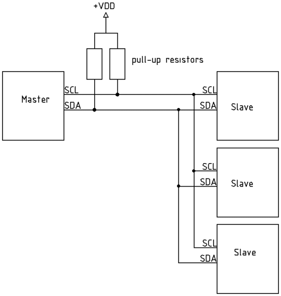
Note that I2C needs a Master and a Slave device for communication to occur. I2C can have multi-master or multi-slave setups, although multi-slave setups are more frequently used. There might be special requirements if you do multi-master setups.
With a multi-slave setup, a master starts a transaction and finds its target slave device by writing the slave’s correct address on the I2C bus. Only the slave with the correct address will acknowledge the master. Hence other slave devices will ignore or NACK this request.
Upon acknowledgment of the correct slave device, several other transactions can follow. These transactions could be single or multiple byte reads or writes, still initialized by the master. These operations determine what kind of slave device you are using.
Here is a typical I2C read waveform from a slave device using a logic analyzer with a protocol analyzer function.
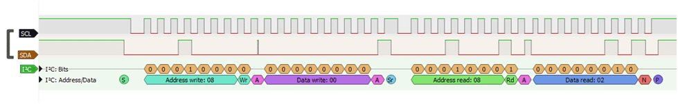
This waveform contains different states and levels on the SCL and SDA lines both of which define different states in the I2C protocol:
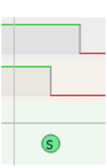
A start bit that initiates the start of any I2C transaction.
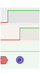
A stop bit that ends every I2C transaction.
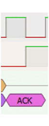
An Acknowledge bit for every address or data reads or writes.
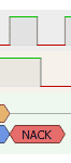
A not acknowledge bit for not acknowledging address or data reads or writes.
The next part will learn more about these states and the I2C protocol.
The Serial Protocol of I2C
Most serial interfaces employ a standard protocol to effectively deliver their messages in a reliable way with minimal issues. I2C is no exception. Here we’ll discuss the I2C protocol for you to understand.
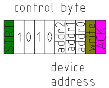
A Master usually initiates the first transaction and starts with a bit. This is followed by a preamble (1010), the device address, and a write bit. This is called the control byte and should be acknowledged by the addressed slave so that continuous byte reads or writes can proceed.
Once the slave acknowledges, a series of transactions occur that depend on your device’s state machine.
Consider reading single or multiple bytes from a slave EEPROM device.
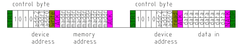
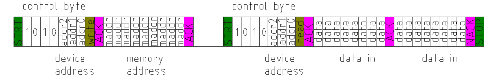
The control byte is sent, followed by an acknowledgment by the slave. Next, the master sends the memory location to read from the slave. This is followed by an ACK on the slave side. The next step is to fetch the data from that memory location. Accordingly, another control byte is written by the master to the slave, now with a read bit, which is also ACK’ed by the slave. Once the ACK is accepted, the master relinquishes control of the SDA line to the slave as the slave clocks in the data to the master. Each data byte transfer must be ACKe’d by the master. On the ninth clock pulse after the last data byte, a NACK occurs (by the master floating the SDA line and letting the slave act on it), indicating that it’s the last data byte transfer needed by the master (or a possible overflow or neglected data from the slave can also occur); thereafter, a stop bit is generated by the master as it does not need more data, indicating the end of the whole transaction.
Confluently, a byte write is similar to a byte read in several aspects. In a byte write, however, the master doesn’t need to clock in data and restart to send the control byte, as seen below.
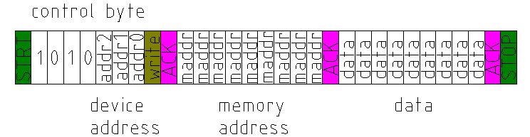
The processes shown above are for byte reads and writes on an 8-bit memory addressed EEPROM. This process extends to any device with an I2C interface, changing only the number of bytes read or written or if there is a need to access a memory location or not. The next part discusses several applications of I2C.
What are I2C's Applications, Advantages and Disadvantages?
Like an EEPROM, I2C applications extend to several peripherals such as OLEDs, LCDs, accelerometers, temperature sensors, and a whole lot more. Because it uses only two wires as its interface, you can save a lot of space on your boards.
A disadvantage of I2C can be that it has a limited speed compared to other serial protocols. Although newer I2C speed standards are coming up, a high-speed I2C will only run at a clock rate of 400 kHz, quite slow compared to SPI, which can run at clock speeds in the MHz range. I2C speed is limited by what its open-drain driver can handle as it employs bi-directional communication.
Additionally, the length of traces that I2C can handle is limited to intra-board communication. This means you can only use I2C with chips communicating on a single board. It is not the intention of I2C to run on long lengths of cables, unlike what you can do with EUSART, for example.
Code Examples
Fortunately, all the messy I2C protocols are abstracted from the user for Arduino. However, if you’d like to know what’s going on, continue reading Part 1 and Part 2 of this article. You’ll never know if you might need low-level debugging, especially if you have a new I2C device that encounters an issue.
Here is a simple master I2C code that writes the character ‘X’ on the I2C bus every second.
					#include <Wire.h>
byte toggle;

void setup() {
  // put your setup code here, to run once:
  pinMode(LED_BUILTIN, OUTPUT);
  Wire.begin();

}

void loop() {
  // put your main code here, to run repeatedly:

  Wire.beginTransmission(8);
  Wire.write("X");
  Wire.endTransmission();

  if(toggle == 1)
    digitalWrite(LED_BUILTIN, HIGH);
  else
    digitalWrite(LED_BUILTIN, LOW);

  toggle ^= 1;

  delay(1000);
}
Wire.begin( ) initializes the I2C master peripheral. To begin transmission Wire.beginTransmission(8) is executed. Parameter 8 is the address of the slave. As we check the protocol, this is the control byte written on the I2C bus.
The code continues to write a character on the line, which signifies a byte write (without a corresponding memory address) on the protocol.
Here is the slave code that receives the character ‘X’.
					#include <Wire.h>

volatile byte received = 0;
char c;
byte toggle;

void setup() {
  // put your setup code here, to run once:
  pinMode(LED_BUILTIN, OUTPUT);
  Serial.begin(9600);
  digitalWrite(LED_BUILTIN, LOW);
  Wire.begin(8);
  Wire.onReceive(receiveEvent);
}

void loop() {
  // put your main code here, to run repeatedly:
  if(received)
  {
    if(c == 'X')
    {
      Serial.println(c);
      if(toggle)
        digitalWrite(LED_BUILTIN, HIGH);
      else
        digitalWrite(LED_BUILTIN, LOW);

      toggle ^= 1;
    }
    received = 0;
  }

}

void receiveEvent(int howMany) {
int i;
  for(i=0;i<howMany;i++)
  {
    c = Wire.read();
  }

  received = 1;
}
Wire.begin(8) sets up the I2C peripheral with slave address 8. Then a receiveEvent( ) function is registered with the I2C receive operation using the Wire.onReceive(receiveEvent) statement. Notice that the receiveEvent( ) function has an integer parameter called howMAny. This parameter counts the number of bytes received by the slave. Consequently, you can use this parameter to coherently retrieve data from the I2C buffers. With this, we used a for-loop to execute the Wire.read( ) function. Once we have received the data on this I2C event, we go back to the main loop to process it.
Same as the previous code, the I2C protocol utilized here is the byte write, where the master writes data to the slave. The slave should act accordingly to this as a receive event, acknowledging each byte that is written by the master.
On a different note, below is a sample code from a master requesting data from a slave.
					#include <Wire.h>
char c;
byte toggle;

void setup() {
  // put your setup code here, to run once:

  pinMode(LED_BUILTIN, OUTPUT);
  Serial.begin(9600);
  Wire.begin();

}

void loop() {
  // put your main code here, to run repeatedly:

  Wire.beginTransmission(8);
  Wire.requestFrom(8, 1);
  while(Wire.available())
  {
    c = Wire.read();
  }
  Wire.endTransmission();

  Serial.println(c);

  if(toggle == 1)
    digitalWrite(LED_BUILTIN, HIGH);
  else
    digitalWrite(LED_BUILTIN, LOW);

  toggle ^= 1;

  delay(1000);
}
Here, the Wire.beginTransmission(8) functions the same as the previous code that writes a character to the slave. Next, a Wire.requestFrom(8, 1) statement executes to request (or read) data from a slave. Parameters 8 and 1 are the slave address and the number of data to read, respectively. In the protocol, this functions as a control byte with the read bit enabled. After that, a character read executes through the Wire. read( ) function while checking how many data reads to do to the slave. This piece of code functions similarly to the read byte function of the protocol in Part 2 (without memory addresses).
Lastly, here is the slave code that gives the character data to the master when the master requests it.
					#include <Wire.h>

volatile byte requested = 0;
char c;
byte toggle;

void setup() {
  // put your setup code here, to run once:
  pinMode(LED_BUILTIN, OUTPUT);
  Serial.begin(9600);
  digitalWrite(LED_BUILTIN, LOW);
  Wire.begin(8);
  Wire.onRequest(requestEvent);
}

void loop() {
  // put your main code here, to run repeatedly:

  if(requested)
  {
    // do other things on request
    if(toggle)
      digitalWrite(LED_BUILTIN, HIGH);
    else
      digitalWrite(LED_BUILTIN, LOW);
    toggle ^= 1;

    requested = 0;
  }

}

void requestEvent() {
    Wire.write("X");
    requested = 1;
}
Here a requestEvent( ) function is registered by Wire.onRequest( ). This function runs automatically when the slave is requested by the master to send its data through the Wire.write( ) function. This code relates to the time when the master relinquishes control of the SDA line for the slave to clock in its data as in Part 2 of this article.
Summary
We demonstrated the inner workings of I2C along with its protocol. We also listed down its applications, advantages, and disadvantages. Lastly, we made sample codes demonstrating the functions of I2C on an Arduino, relating them to the actual I2C protocol.
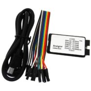
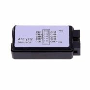
Learning the basics of I2C will be very useful for your projects requiring I2C interfaces. At Phipps Electronics, we have a number of kits and tools to help you with this. Browse through our development tools catalog for more info. For looking closely at your I2C hardware, we recommend using the 8-Channel Logic Analyzer from our Test Equipment section.
SHOP THIS PROJECT
-
Sale!

USB 8 Channel 24MHz Logic Analyser
$32.95Original price was: $32.95.$29.95Current price is: $29.95. Add to cart