Introduction
Shift Registers are monolithic integrated circuits (ICs) that contain several flip-flops. Each of these flip-flops is called a register. Each register stores information in the form of a bit. Shift registers can clock out each bit continuously in a serial fashion and this is what they are known for.
Below is a simple tutorial that will explain how to control the pins of a shift register easily using an Arduino. Yes, that’s right, you don’t have to spend an enormous amount of effort designing a complex circuit to control your shift registers.
SHIFT REGISTER 74HC595 LIBRARY
The shift register library is readily available in the Arduino IDE library. All you have to do is download and install it.
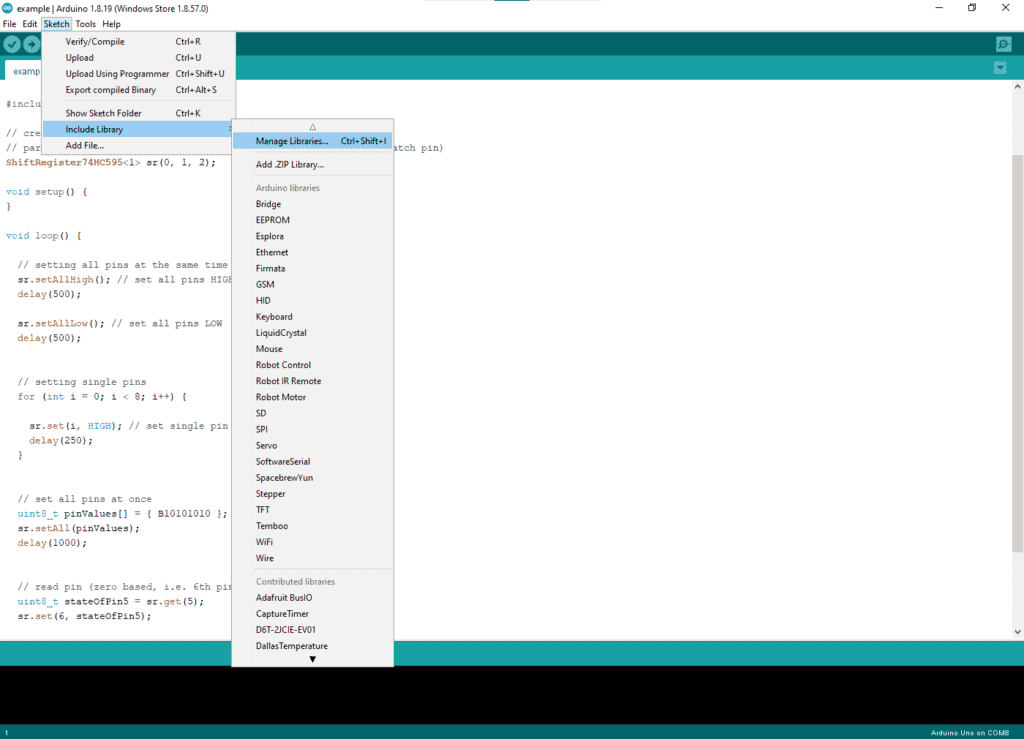
First, go to Sketch->Include Library->Manage Libraries…
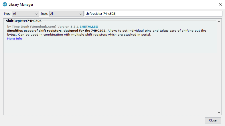
Next, type ShiftRegister 74HC595 and choose the library made by Timo Denk. After that, install it.
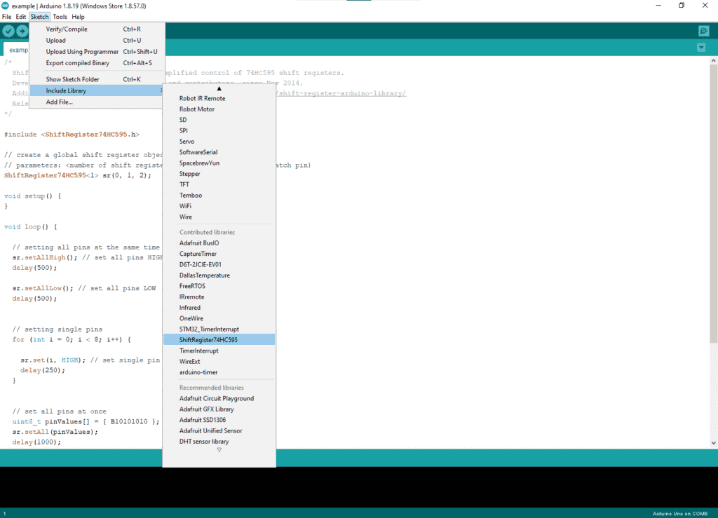
Don’t forget to include it in your code by going to Sketch->Include Library->ShiftRegister 74HC595
Now, let’s implement the circuit below to know how to use the library.
Circuit Diagram
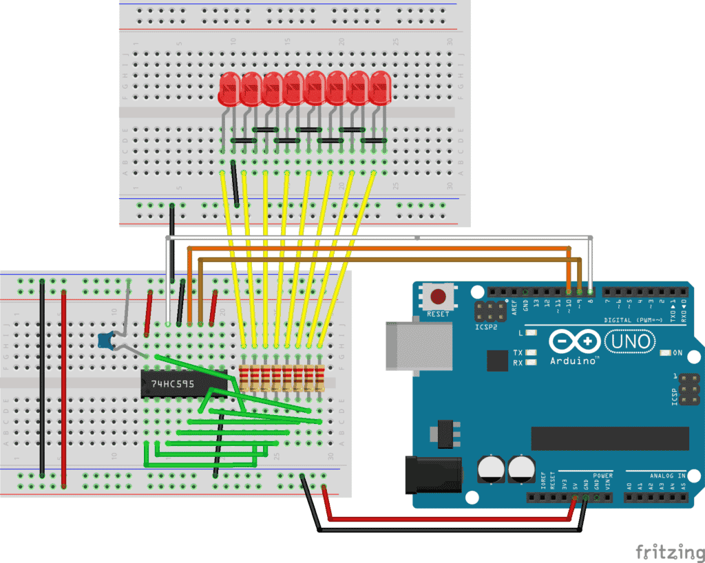
Wire up the circuit above as best as you can. In the circuit, pins 11, 12, and 14 of the 74HC595 can be attached to any of the digital pins of Arduino. In that case, you have to declare the correct pin numbers that you used in the circuit within the code.
After constructing the circuit we can start to program. The library has a few functions and each of them will be explained in detail.
Creating The Object
We start by creating the object. The object needs to be created outside the setup or loop function. So, we start by declaring a few global variables then we create the object:
					#include <ShiftRegister74HC595.h>

int numberOfShiftRegisters = 1; // number of shift registers attached in series

int serialDataPin = 8; // DS
int clockPin = 9; // SHCP
int latchPin = 10; // STCP

ShiftRegister74HC595 sr (numberOfShiftRegisters, serialDataPin, clockPin, latchPin);
We are importing the library in the first line. Next, we associate some shift register pins to the corresponding Arduino pin. Finally, in the last line, we create an object called “sr” using a variable declared previously. We’ll also declare how many shift registers we are using in the first argument. In our case, we are only driving 1 shift register, however, we could also drive several using this same library.
Make sure that, this code segment is always at the top.
Next, we’ll learn how to use some functions for the 74HC595 using the library.
Turning On All The LEDs
					#include <ShiftRegister74HC595.h>

int numberOfShiftRegisters = 1; // number of shift registers attached in series
int serialDataPin = 8; // DS
int clockPin = 9; // SHCP
int latchPin = 10; // STCP

// create shift register object (number of shift registers, data pin, clock pin, latch pin)
ShiftRegister74HC595 sr (numberOfShiftRegisters, serialDataPin, clockPin, latchPin);

void setup() {

Serial.begin(9600);
}

void loop() {

//Set all pins HIGH
sr.setAllHigh();
delay(500);

//Set all pins LOW
  sr.setAllLow();
  delay(500);

}
The setAllHigh( ) and setAllLow( ) functions turns ON and OFF all the LEDs of the 74HC595
Turning pins HIGH and LOW one by one
In this code, we will first turn all the LEDs ON one by one, then turn them off again. The function we will be using for this is set(i, HIGH)
The set( ) function works similarly to the digitalWrite() function. The first argument passed is the pin number. This pin number indicates the output pin numbers of the Shift Register. The 2nd argument is the state you want it to be in (HIGH or LOW).
					#include <ShiftRegister74HC595.h>

int numberOfShiftRegisters = 1; // number of shift registers attached in series
int serialDataPin = 8; // DS
int clockPin = 9; // SHCP
int latchPin = 10; // STCP

// create shift register object (number of shift registers, data pin, clock pin, latch pin)
ShiftRegister74HC595 sr (numberOfShiftRegisters, serialDataPin, clockPin, latchPin);

void setup() {

Serial.begin(9600);
}

void loop() {

//Set pins HIGH one by one
for (int i = 0; i < 8; i++) {
sr.set(i, HIGH); //
delay(250);
}

//Set pins LOW again one by one
for (int i = 8; i >= 0; i--) {

sr.set(i, LOW);
delay(250);
}
}
Configuring The Pins All At Once
This code can change each output pin state all at once with just a few lines.
					#include <ShiftRegister74HC595.h>

int numberOfShiftRegisters = 1; // number of shift registers attached in series
int serialDataPin = 8; // DS
int clockPin = 9; // SHCP
int latchPin = 10; // STCP

// create shift register object (number of shift registers, data pin, clock pin, latch pin)
ShiftRegister74HC595 sr (numberOfShiftRegisters, serialDataPin, clockPin, latchPin);

void setup() {

Serial.begin(9600);
}

void loop() {

//0 and 1s are the pattern you want your LEDs to light up like
uint8_t pinValues1[] = { B10101010 };
sr.setAll(pinValues1);
delay(1000);

uint8_t pinValues2[] = { B01010101 };
sr.setAll(pinValues2);
delay(1000);

}
Read The State of an Output Pin
We can also know the state of output pins using a library function. In this code, we lit up some LEDs. After that, using the sr.get( ) function, we’ll know the current state of the output pin. Next, we’ll write the states of each pin in the serial monitor where 0 means LOW and 1 means HIGH.
					#include <ShiftRegister74HC595.h>

int numberOfShiftRegisters = 1; // number of shift registers attached in series
int serialDataPin = 8; // DS
int clockPin = 9; // SHCP
int latchPin = 10; // STCP

// create shift register object (number of shift registers, data pin, clock pin, latch pin)
ShiftRegister74HC595 sr (numberOfShiftRegisters, serialDataPin, clockPin, latchPin);

void setup() {

Serial.begin(9600);
}

void loop() {
uint8_t pinValues1[] = { B10101010 };
sr.setAll(pinValues1);
delay(1000);

Serial.println(sr.get(4));
Serial.println(sr.get(5));
}
Conclusion
Implementing a circuit having a 74HC595 chip is relatively easy by using the ShiftRegister 74HC595 Arduino library. All it takes are some pin and object declarations at the start of your code. Next, using the library functions will provide all the necessary steps to operate the 74HC595 with ease.


