A BJT is a very popular electronic component. If you want to find out more about it, how it functions, and its applications, read through the rest of this article.
Introduction
Bipolar Junction Transistors (commonly called BJTs) have been in the electronics world since their conception in 1948 (Hoerni). The BJT is a three-terminal semiconductor device that finds so many uses in electronics. They can be used as an electronic switch to turn on loads, as an amplifier to amplify small signals, and as a building block for several Integrated Circuits back then. Most electronics students start learning BJTs as their first logic switch and incorporating them in their first amplifier circuit.
Though BJTs have been surpassed by other transistor technologies in terms of current draw and material density, they are still being widely used today. You’ll likely find one if you open up a complicated consumer electronic device. Consequently, an added benefit of BJTs is that they are more resilient to electrostatic discharge than their FET counterpart.
To learn more about BJT’s composition and application, continue to the following parts.
BJT Composition
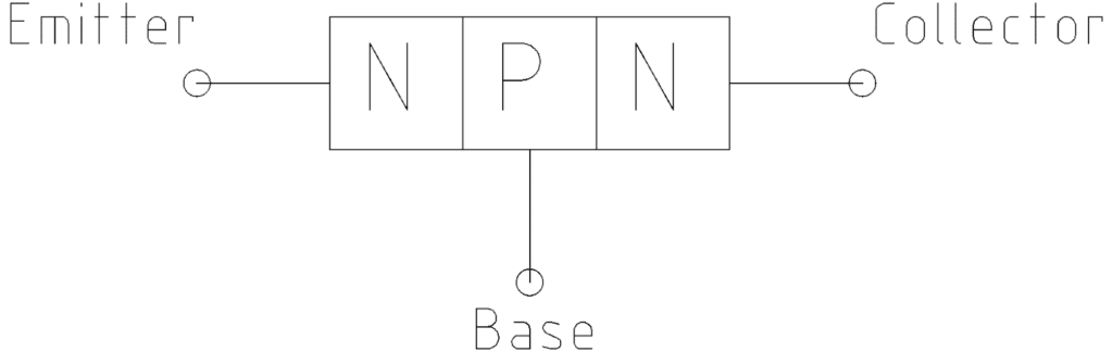
BJTs have three terminals called Emitter, Base, and Collector. Each terminal represents the type of semiconductor used. It’s either an N-type or a P-type material. Every two adjacent terminals represent a junction called a PN junction. Each junction should be biased correctly for proper device operation.
With this, there are two kinds of BJT transistors, namely, the NPN type and the PNP type. They are illustrated below, and they each have their own schematic symbols.
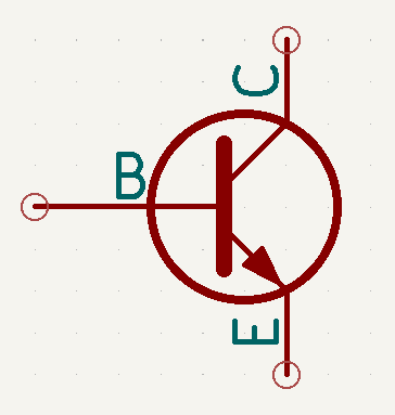
NPN Transistor
Terminals
Schematic Symbol
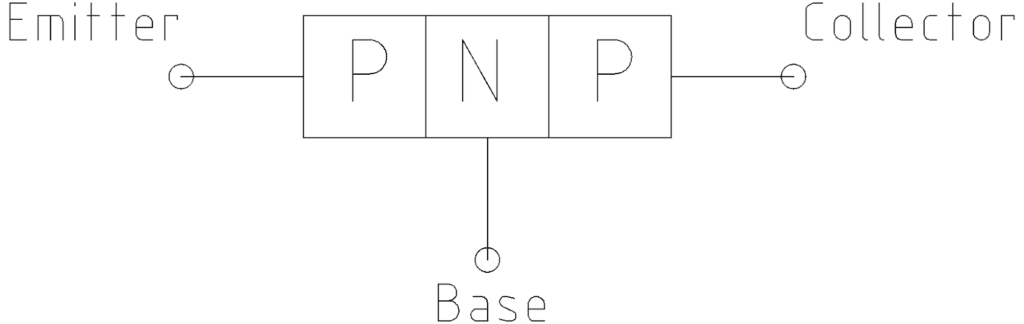
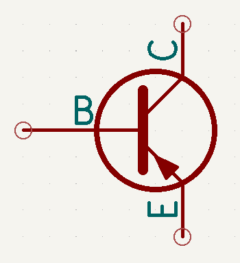
PNP Transistor
Terminals
Schematic Symbol
What are the Uses of a BJT?
A BJT transistor can be used as an electronic switch or a signal amplifier.
BJT as an Electronic Switch
As a switch, you’ll need to forward bias the base-emitter junction with a voltage greater than 0.7V to turn it on. After overcoming this 0.7V threshold, the collector-emitter loop will begin to allow a generous amount of current flow. This current flow can power up a load and is only limited by the load’s resistance and the applied voltage. Ensure your transistor can handle the current and voltage required by your load.
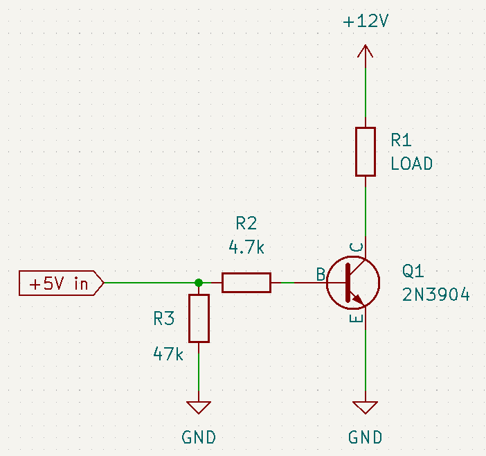
Here is a basic NPN transistor used as a low-side switch. Low-side because the switching element (transistor Q1) is on the low side of the load and also directly connected to the ground. R1 is the load and can be an LED or another peripheral. R2 is the base resistor that limits the base current, while R3 is there simply to pull down the base-emitter voltage to a low level when the base terminal is left floating.
When the input goes beyond 0.7V (+5V in this example), a base current will flow. This base current will be multiplied by several magnitudes and will be reflected on the collector-emitter side as collector current Ic. If the collector current is limited by the load’s resistance and the voltage supply (+12V), the transistor is said to be in saturation. Saturation mode is the ideal mode for a transistor to be used as an electronic switch.

If your load is a motor or has inductive properties, there needs to be a diode connected in parallel to your load to act as a protection device. This diode will effectively block back-EMF signals that can destroy your transistor or your controlling circuit. These back-EMF signals are high-voltage transients that happen as you turn off your BJTs coming from the ON state. This happens due to the inductor storing energy in the form of current. When you release the transistor from the ON state, that energy finds a path through your transistor and increases in voltage. However, if you have the back-emf diode installed, the path will be shorted out and the transient will be absorbed by the body of the diode.
BJT as an Amplifier
An amplifier amplifies a small signal to a larger signal. The most common configuration for a BJT used as an amplifier is the common emitter configuration. Common emitter means that the emitter is common to both the input and output signals.
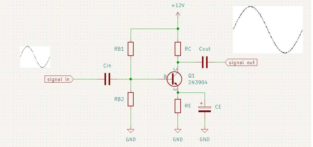
The figure above is an example of this. This is called a Beta independent voltage divider transistor amplifier. Beta is a symbol to represent the current amplification factor ratio between the collector current Ic and the base current Ib. Beta is the reason we have amplification in a transistor circuit.
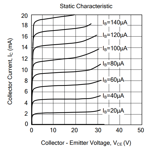
It is important to note that you should operate a BJT in the linear region when using it as an amplifier. Above, you can see a graph of a transistor characteristic curve of the popular 9013 transistors. You can use a similar graph like this to find the linear region of your transistor. The linear region is usually near the centre where there is no distortion on the graph.
In order to get to the linear region, you should bias the BJT. Figure 7 illustrates this. There are four resistors used as biasing elements, namely RB1, RB2, RC, and RE. The voltage divider RB1 and RB2 adjust the base current Ib. This also has the potential to stabilize the Beta of the circuit. RC biases the collector current by defining the Vce or collector-to-emitter voltage of the circuit. Lastly, there is RE. RE is an emitter stabilizer. Its function is to stabilize Beta. It also helps the amplifier circuit to lessen the effect of temperature on several of its parameters.
Additionally, there are 3 capacitors in the circuit. Cin and Cout bocks DC voltage so that only AC signals pass through the inputs and outputs. CE is part of the emitter stabilizer circuit. It allows AC current to be amplified but rejects the DC component.
As you can see, a small signal on the input is amplified by several magnitudes at the output. The factor by which voltage is amplified is called the gain of the circuit.
Conclusion
BJTs are useful electronic devices that can be used as a switch or an amplifier in your circuits. They are often the first type of transistor device to be taught in schools. If used as a switch, make sure your transistor is up to spec with your load. Also, make sure to use protective diodes when driving motors or inductive loads. Simple amplifier circuits can be illustrated easily using BJTs. Make sure to look at your transistor datasheet to be able to set your parameters safely and correctly.
Work Cited
Hoerni, Jean. “Bipolar junction transistor.” Wikipedia, https://en.wikipedia.org/wiki/Bipolar_junction_transistor#History. Accessed 20 September 2022.


