Have you tried the nRF24L01 radio transceiver module from Nordic Semiconductors? Interested to know how it runs? This article will guide you on how to send and receive data on this device.
Introduction
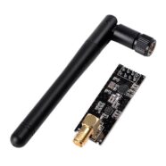
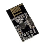
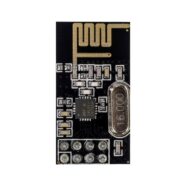
One of Nordic Semiconductors’ flagship products is the nRF24L01. It’s still a popular wireless transceiver module (meaning it can both wirelessly transmit and receive data) even though it was released several years ago. Many hobbyists find this chip reliable and efficient when they’re doing wireless. You’ll be surprised at the amount of info available on the net regarding this. Though Nordic officially stopped development tool support for this product in lieu of its newer products (the nRF52810 for example), it will still be available through the nRF’s long term parts availability statement.
The nRF24L01’s latest silicon version is the nRF24L01+. It has improved wireless transmission parameters than its predecessor. Both versions, though, could satisfactorily accomplish simple wireless tasks.
NRF24L01+ Capabilities
The nRF24L01+ is a 2.4 GHz wireless transceiver that operates through SPI (Serial Peripheral Interface). You’ll be able to work on several internal registers in this device through SPI by using only an MCU. You can go as fast as 10MHz on the SPI clock and use the three-level FIFO during both the transmit and receive cycles.
The module can transmit and receive data wirelessly through its built antenna port. You can only transmit or receive (but not both) at any given moment. It has a special piping capability wherein you can have six transmitters talking to 1 receiver through the Multiceiver approach. Each transmitter should have its own unique address, and this should be matched with the receiver.
The nRF24L01+ can work in low (250 kbps), medium (1 Mbps), or fast (2Mbps) data rates. It has its own data link layer called Enhanced Shockburst. Enhanced Shockburst takes care of all low-level wireless processes. It also abstracts other wireless transmission/receiving states so that the user can concentrate on his application. Consequently, Enhanced Shockburst tries to be flexible in its approach and allows users to customize their transmit, receive and acknowledge operations.
Here are the specs of nRF24L01+ in a list:
- Worldwide 2.4GHz ISM band operation
- Up to 2Mbps on-air data rate
- Ultra-low power operation
- 11.3mA TX at 0dBm output power
- 12.3mA RX at 2Mbps air data rate
- 900nA in power down
- 22μA in standby-I
- On-chip voltage regulator
- 1.9 to 3.6V supply range
- Enhanced ShockBurst™
- Automatic packet handling
- Auto packet transaction handling
- 6 data pipe MultiCeiver™
- 5V tolerant inputs
- 4-Pin SPI Interface, 3-level FIFO, up to 10MHz clock
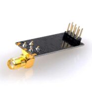
Pin Out
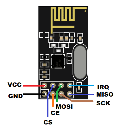
| PINS | NAME | FUNCTION |
|---|---|---|
| 1 | VCC | Supply Voltage |
| 2 | GND | Ground |
| 3 | CE | Chip Enable |
| 4 | CS | Chip Select |
| 5 | SCK | SPI Clock |
| 6 | MOSI | Master Out Serial In Data |
| 7 | MISO | Mater in Special Out data |
| 8 | IRQ | Interrupt Request Pin |
Wiring Diagram
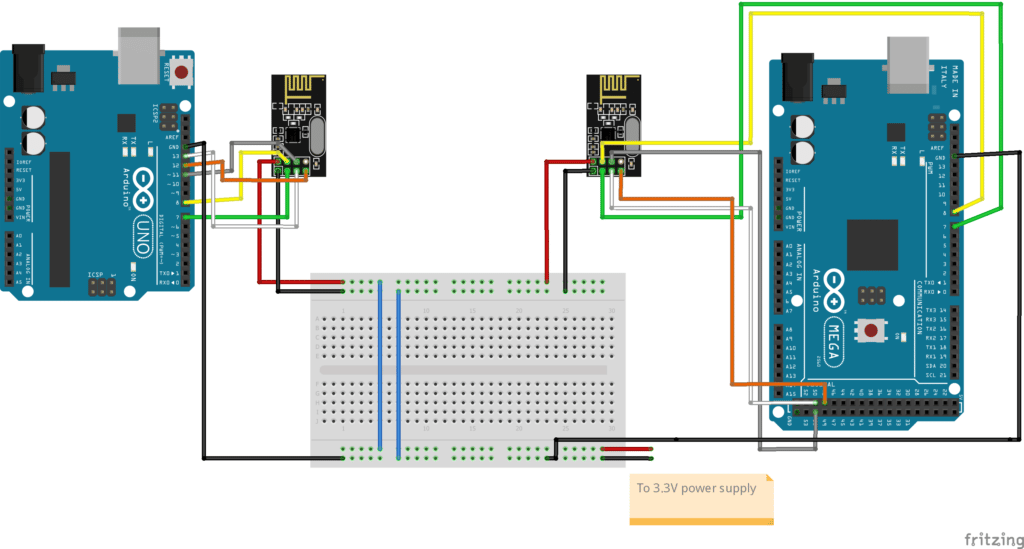
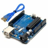
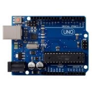
Wire the UNO and the MEGA to the nRF2401+ modules, as seen above
The nRF24L01+ module is interfaced via SPI. With this, you’ll have to find the SPI ports of your Arduino.
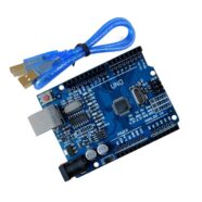
Here are the SPI ports for the Arduino UNO:
| CS | 10 |
| SCK | 13 |
| MOSI | 11 |
| MISO | 12 |
Here are the SPI ports for the MEGA 2560:
| CS | 53 |
|---|---|
| SCK | 52 |
| MOSI | 51 |
| MISO | 50 |
The nRF module has a CE pin that’s used to power up the transmit radio. You can use any extra digital port for this.
The IRQ pin is exclusively used for more precise, hardware-based packet handling. Since we’ll be dealing with this in the firmware, you can omit connecting this pin.
You may wonder why we didn’t connect the 3.3V power supply of the Arduino boards directly to the nRF modules. Instead, we connected it to a separate power supply. The reason for this is the nRF24L01+ runs in burst mode when transmitting data. This burst mode can get a hefty amount of current from the power supply for brief moments. The Arduino boards have a simple power supply layout that might not be suited for this. Hence, a separate power supply was provided.
After wiring it up, you can continue to write code in the Arduino IDE.
The Code
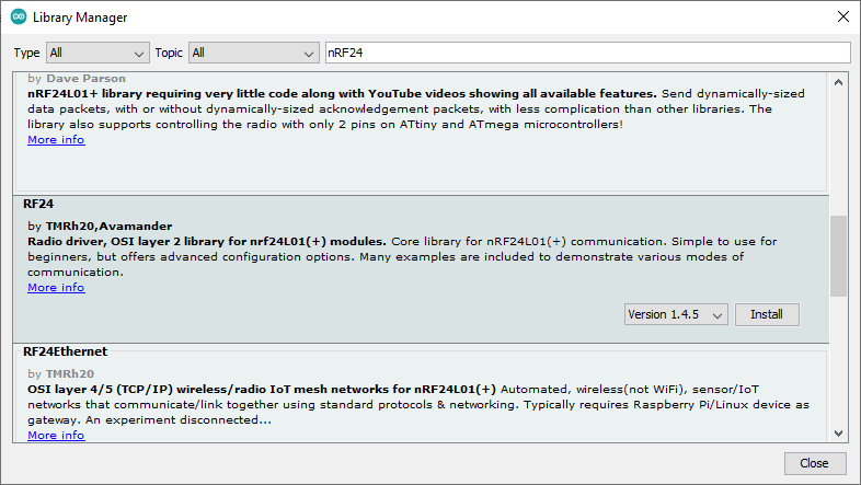
Since we are writing for the Arduino IDE we must download a library for the nRF24L01. An interesting library to download is the RF24 by TMRh20 and Avamander. It’s really simple to use and has been tested through time.
Go to Tools -> Manage Libraries… then search for nRF24 to be able to download it.
The Getting Started example firmware is a good place to start studying nRF24L01 firmware. You can find this by going to File -> Examples -> RF24 -> Getting Started.
We’ll use the Getting Started firmware as the base for our code.
What are we going to do:
We’ll write a simple transmitter code for the UNO and a receiver code for the MEGA 2560. Hopefully, this will help the reader understand basic transmitter and receiver functions on the nRF24L01+
Here is the transmitter code using the UNO:
You can download the Arduino code here.
First, include the necessary headers using Sketch -> Include Library and search for RF24.
					#include <nRF24L01.h>
#include <printf.h>
#include <RF24.h>
#include <RF24_config.h>
Next, instantiate the RF24 object as a radio with some pin parameters. The addressing scheme is abstracted away from the user through nodes. You’ll be able to determine a proper transmit and receive pair through this. Then we declare the payload variable as float and a led_state flag as a byte.
					// instantiate an object for the nRF24L01 transceiver
RF24 radio(7, 8);  // using pin 7 for the CE pin, and pin 8 for the CSN pin

// Let these addresses be used for the pair
uint8_t address[][6] = { "1Node", "2Node" };
// It is very helpful to think of an address as a path instead of as
// an identifying device destination

// to use different addresses on a pair of radios, we need a variable to
// uniquely identify which address this radio will use to transmit
bool radioNumber = 1;  // 0 uses address[0] to transmit, 1 uses address[1] to transmit

// For this example, we'll be using a payload containing
// a single float number that will be incremented
// on every successful transmission
float payload = 0.0;

byte led_state = 0;
The setup code sets up the serial port. It initializes the transceiver and sets the PA (Power Amplifier) of the antenna. Then it readies the payload size to use.
Next, a piping scheme is implemented. A receiver usually transmits an ACK packet after being transmitted to. Through transmit pipe 0 we’ll be able to do this. By default, two pipes are enabled on the nRF24L01, and we’ll see the other pipe in the receive code next. Lastly, we put the radio in transmit mode.
					void setup() {
  // put your setup code here, to run once:
  Serial.begin(115200);
  while (!Serial) {
    // some boards need to wait to ensure access to serial over USB
  }

  // initialize the transceiver on the SPI bus
  if (!radio.begin()) {
    Serial.println(F("radio hardware is not responding!!"));
    while (1) {}  // hold in infinite loop
  }

  // print example's introductory prompt
  Serial.println(F("Let's start transmitting"));

  // Set the PA Level low to try preventing power supply related problems
  // because these examples are likely run with nodes in close proximity to
  // each other.
  radio.setPALevel(RF24_PA_LOW);  // RF24_PA_MAX is default.

  // save on transmission time by setting the radio to only transmit the
  // number of bytes we need to transmit a float
  radio.setPayloadSize(sizeof(payload));  // float datatype occupies 4 bytes

  // set the TX address of the RX node into the TX pipe
  radio.openWritingPipe(address[radioNumber]);  // always uses pipe 0

  radio.stopListening();  // put radio in TX mode

}
The Loop code consists of choosing a payload and then writing it to the radio for transmission. The report variable determines if the transmission was properly acknowledged by the receiver.
					void loop() {
  // put your main code here, to run repeatedly:
  bool report;

  if(led_state == 0)
  {
    payload = 1.00;
  } else {
    payload = 2.00;
  }

  report = radio.write(&payload, sizeof(float));  // transmit & save the report

  // switch led_state
  led_state ^= 1;


  if(report) {
    Serial.print(F("Transmission successful! "));  // payload was delivered
    Serial.print(F("Sent: "));
    Serial.println(payload);  // print payload sent
  }

  delay(1000);  // slow transmissions down by 1 second
}
Here is the receiver code:
You can download the Arduino code here.
As in the transmitter code, radio instantiation is done. Next, radioNumber is now given the value 0 to identify it as a receiver.
					// instantiate an object for the nRF24L01 transceiver
RF24 radio(7, 8);  // using pin 7 for the CE pin, and pin 8 for the CSN pin

// Let these addresses be used for the pair
uint8_t address[][6] = { "1Node", "2Node" };
// It is very helpful to think of an address as a path instead of as
// an identifying device destination

// to use different addresses on a pair of radios, we need a variable to
// uniquely identify which address this radio will use to transmit
bool radioNumber = 0;  // 0 uses address[0] to transmit, 1 uses address[1] to transmit

// For this example, we'll be using a payload containing
// a single float number that will be incremented
// on every successful transmission
float payload = 0.0;
The setup code sets a status LED, initializes the serial port, and initializes the radio.
Then the PA is set as well as the payload size.
Next, a receiving pipe (pipe 1) is used to set the receive address of the transmitter node into this receive pipe. The last statement readies the chip in receiver mode.
					void setup() {
  // set LED
  pinMode(LED_BUILTIN, OUTPUT);
  // put your setup code here, to run once:
  Serial.begin(115200);
  while (!Serial) {
    // some boards need to wait to ensure access to serial over USB
  }

  // initialize the transceiver on the SPI bus
  if (!radio.begin()) {
    Serial.println(F("radio hardware is not responding!!"));
    while (1) {}  // hold in infinite loop
  }

  // print example's introductory prompt
  Serial.println(F("Let's start transmitting"));

  // Set the PA Level low to try preventing power supply related problems
  // because these examples are likely run with nodes in close proximity to
  // each other.
  radio.setPALevel(RF24_PA_LOW);  // RF24_PA_MAX is default.

  // save on transmission time by setting the radio to only transmit the
  // number of bytes we need to transmit a float
  radio.setPayloadSize(sizeof(payload));  // float datatype occupies 4 bytes

  // set the RX address of the TX node into a RX pipe
  radio.openReadingPipe(1, address[!radioNumber]); // using pipe 1

  radio.startListening();  // put radio in RX mode

}
The loop code, as you can see, is waiting in receive mode. Once the receive address is matched (as what has been set up in the radio.openReadingPipe(1, address[!radioNumber]) statement), the code continues to receive the payload and process the values by blinking an LED.
					void loop() {
  // put your main code here, to run repeatedly:
  bool report;
  uint8_t pipe;

  if (radio.available(&pipe)) {              // is there a payload? get the pipe number that recieved it
    uint8_t bytes = radio.getPayloadSize();  // get the size of the payload
    radio.read(&payload, bytes);             // fetch payload from FIFO
    Serial.print(F("Received "));
    Serial.print(bytes);  // print the size of the payload
    Serial.print(F(" bytes on pipe "));
    Serial.print(pipe);  // print the pipe number
    Serial.print(F(": "));
    Serial.println(payload);  // print the payload's value

    if(payload == 1.00)
      digitalWrite(LED_BUILTIN, HIGH);

    if(payload == 2.00)
      digitalWrite(LED_BUILTIN, LOW);
  }


}
Conclusion
The nRF24L01 is a reliable and easy-to-use transceiver module from Nordic Semiconductor. It’s still a marketable device that’s loved by many electronics hobbyists, even though it has been in the industry for quite a long time. Writing firmware in the Arduino environment on this device is easy. Wire it up, download its library, and you’re all set to talk with your devices wirelessly.
SHOP THIS PROJECT
-
Sale!

UNO R3 ATmega328P CH340 Development Board – Arduino Compatible with USB Cable
$23.95Original price was: $23.95.$22.95Current price is: $22.95. Add to cart