Have you tried working on SPI on an Arduino? Want some guidance on how to use its libraries and functions? Continue reading the rest of the article to find out.
Introduction
The SPI or Serial Peripheral Interface is a serial protocol used between electronic devices so that they can communicate with each other. It’s like I2C (Inter-integrated Communication) or UART(Univeral Asynchronous Receiver Transmitter). The main advantage of using SPI with regard to I2C or UART is its speed. SPI is limited by your main oscillator but can reach speeds of up to 50 MHz. The main disadvantage of SPI is the number of wires it needs to communicate. You’ll usually need 4 wires with SPI. It’s more compared with I2C (which needs 2 lines, SCL and SDA) and UART (which also needs 2 lines, TX and RX).
So, where do you use SPI, and what are its practical uses? Because SPI is fast compared to other protocols, it’s used to transfer digital data with a bit more complex operations in real-time. Examples of these operations are Accelerometers, Analog-to-Digital Converters, Digital Potentiometers, Wireless communications ICs, and the like. It’s also used in EEPROMS and SD cards as a serial interface because it can speed up storing digital data. Once you learn to use SPI, you’ll be satisfied with its simplicity, robustness, and speed.
Wiring Diagram
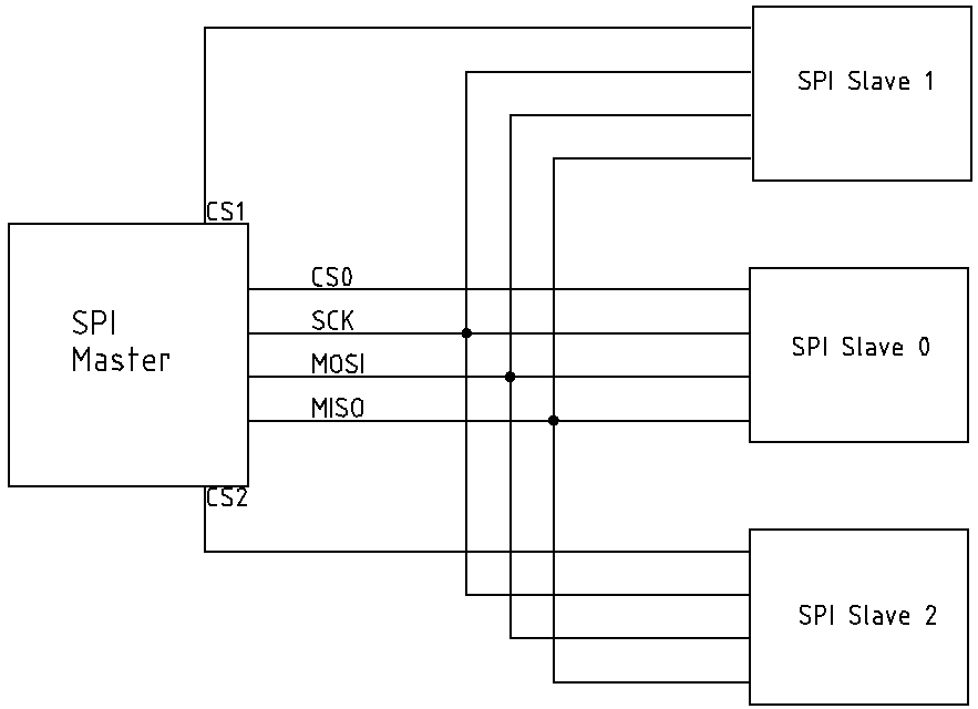
The SPI protocol needs a master device to initiate communication and a slave device to accept this communication.
As can be seen in the figure above, SPI needs at least four wires to communicate with devices.
The four wires are:
CS or Chip Select
SCK or Serial Clock
MOSI or master Out Serial In
MISO or Master in Serial Out
Chip Select lines are usually free GPIO ports on a microcontroller. Otherwise, a dedicated pin is used. The user sets one CS to an active level to be able to select a slave chip to communicate with. All other lines are left inactivated. The level should be maintained until the entire SPI transaction completes.
The Serial Clock is the main output clock of SPI. With this line, you’ll be able to store or receive data synchronously with your devices. It goes along and is in sync with the MISO and MOSI lines. It’s usually generated by the MCU or processor to synchronously communicate with SPI slave devices.
The MOSI line, as its name implies, outputs data from the master to a slave device. These data should be in-sync with SCK.
The MISO line, as its name implies, outputs data from the slave to a master device. These data should also be in-sync with SCK.
Sample Waveform
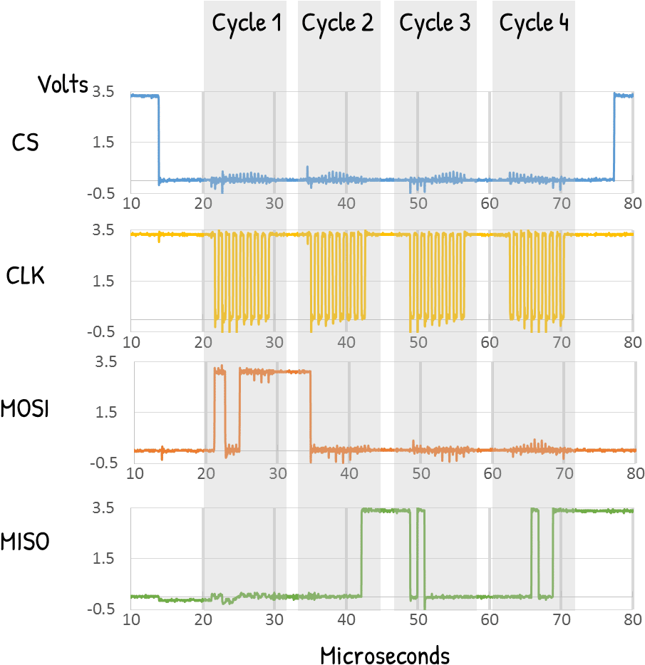
Here is a sample waveform of an SPI. As you can see, the CS line is active low during an entire SPI transaction. There are bursts of 8-bit serial clock cycles of SCK’s in that period. At this time, data from the MOSI and MISO lines are being clocked in and clocked out from the slave SPI devices.
SPI Modes
There are varieties of using the SPI SCK, MOSI, and MISO lines. They are called Modes of SPI. Different devices may have different modes of use. However, many try to stick to a standard. Their difference lies in the SCK’s active level combined with at what phase data is sampled from the MOSI and MISO lines.
| SPI MODE | CPOL | SCK Polarity | CPHA | SCK Sampling Phase |
|---|---|---|---|---|
| 0 | 0 | SCK is Active High | 0 | Data sampled at the Rising edge |
| 1 | 0 | SCK is Active High | 1 | Data sampled at the Falling edge |
| 2 | 1 | SCK is Active Low | 0 | Data sampled at the Rising edge |
| 3 | 1 | SCK is Active Low | 1 | Data sampled at the Falling edge |
How To Use SPI
Different microcontrollers have different libraries for SPI. On the lowest level of operation, registers are being used.
Here is a general format on how MCUs work with SPI
- First, you’ll need to define the ports, clock speed, and mode of operation of SPI.
- After that, initialize the SPI module.
- Enable the SPI slave by giving out the appropriate CS level on that port.
- Next, begin a single or several SPI transactions.
- Finally, you can terminate the SPI transaction
- Bring back the CS line to the inactive state.
Here are sample transactions of SPI in Arduino:
First, include the SPI library:
#include <SPI.h>
Next, define a GPIO port to be the CS pin, then set it up in your setup code:
					#define CS 2

setup()
{
…
  pinMode(CS, OUTPUT);
…
}
Then set your SPI settings with a new object called MySPISettings:
MySPISettings SPISettings(SPI Clock Speed, SPI Data Order, SPI Mode)
SPI Clock speed is the fastest clock speed your SPI can use. It will automatically be adjusted by the library to go lower or at that speed. So, for example, your Arduino runs at 15 MHz, then put in 15000000.
SPIData Order – For your data order, choose from the constant settings below:
MSBFIRST
LSBFIRST
The most common setting for SPI is MSB first
SPI Mode – For your SPI mode, choose from the constant settings below:
SPI_MODE0
SPI_MODE1
SPI_MODE2
SPI_MODE3
This was explained in the previous part. The most common SPI Mode is Mode 0.
You can now begin transacting with your SPI with the following statement:
SPI.beginTransaction(MySPISettings)
Next, get your CS Gpio port pin to its active state. Here we are putting it low to make it active.
digitalWrite(CS, LOW);
After that, declare a byte variable to hold your SPI data. Note that SPI is a bi-directional communication protocol, meaning it sends and receives data simultaneously. This is why you need to store data even though you are just transferring data to a slave device.
Start your first SPI transfer by using the SPI.transfer() function.
					byte receivcedData;
receivedData = SPI.transfer(0x0A);
ere we are sending the value 0x0A to a slave device while waiting for the receivedData value also from the slave.
There are several variations in the SPI.transfer() function. You can use the SPI.transfer16 function to transfer 2 bytes of data in one statement. You can also use SPI.transfer(buffer, size) to transfer more than a byte or two of data while declaring its size. Note that in this statement, the buffer will be replaced with incoming data.
After this and several transactions, if you are finished sending data, deactivate the slave by deactivating the CS pin as:
digitalWrite(CS, HIGH);
Finally, you can end the SPI transaction with:
SPI.endTransaction();
Conclusion
SPI is a simple yet effective serial interface to communicate with other devices. It can be clocked at higher speeds compared with other standard serial interfaces like I2C or UART. It usually needs 4 lines to communicate, namely, CS, SCK, MOSI, and MISO. The CS line is used to select the slave device it wants to communicate with.
To use SPI with Arduino, simply include the SPI.h library file in your source code. Setup your SPI settings using SPISettings() and begin your SPI transaction with SPI.beginTransaction(). After activating your CS line, you can use the SPI.transfer() functions to move data between your devices. Deactivate your CS line afterwards and then end your SPI transaction with SPI.endTransaction().