Do you need an oscilloscope for your projects but don’t want to by an expensive device? Are you willing to explore how the RPI Pico can help? Read through this article to find out more about turning your RPI Pico into a neat oscilloscope.
Introduction
An oscilloscope is an essential part of any electronics workbench. This tool can help you troubleshoot problems or understand certain behaviours in an electronic circuit. Having one presents a status that you’re really into your field. If you have a friend who owns an oscilloscope, you probably look up to him and rely on some of his capabilities or services.
Sometimes, you may get jealous of people who own an oscilloscope. The price tag of this modern equipment is no joke. An oscilloscope consists of precise electronics both in the analog and digital domains. In the early days, it was mostly analog oscilloscopes. Everything had to be calibrated both visually and according to specs. When digital scopes came out, it was much easier to operate. You can now rely on automatic calibration mechanisms and digital read-outs that make life easier.
As chips got smaller, so did the number of transistors inside them. For this reason, modern digital storage oscilloscopes have become more versatile, mobile, and easier to integrate.
With this development, modern microcontrollers are becoming more powerful. Microcontroller-based oscilloscopes are on the rise. Your RPI Pico is a part of this. So get ready to turn it into a mini oscilloscope with your smartphone. Your RPI Pico will now become more practical in your workbench.
The RPI Pico Capabilities
The RPI Pico contains an RP2040 Arm Cortex M0+ processor. It’s a 32-bit dual-core processor that’s clocked at 133MHz. It has a lot of RAM at 264KB. Best of all, the Pico is equipped with external onboard flash memory with 2MB storage space.
Here are its other specs:
-
26 * GPIO pins
-
2 * SPI
-
2 * I2C
-
2 * UART
-
3 * ADC input ports (12-bit)
-
A Temp sensor (can be made as an ADC input)
-
8 * Programmable PIO
-
USB (1.1) device and host
-
On-chip timer and clock
The RPI Pico’s ADC is a SAR-type ADC (Successive Approximation Register). It has a 500ksps sampling rate when using a 48MHz clock. It can sample up to a 12-bit resolution. It has a total of 4 multiplexed input sources which include the 3 GPIO inputs and an internal temperature sensor.
These specs say that the RPI Pico can genuinely be used as a mini digital storage oscilloscope. The ADC sampling speed (at 500ksps) is just enough to make medium-speed acquisitions. The processor and RAM will be useful to store digital data, while the USB port is a good interface for smartphones or mobile devices.
Materials
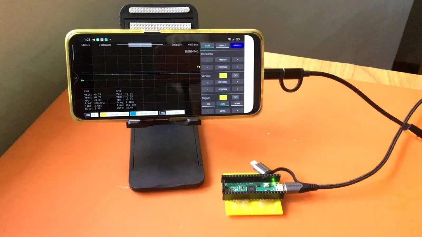
You’ll need an RPI Pico, the Scoppy App (for Android), a USB OTG adapter, and a micro USB cable.
It’s necessary to have a USB OTG adapter and a micro USB cable to be able to run Scoppy with your RPI Pico. Your mobile device will power up the Pico board and send and receive data through this interface. So be ready to enable USB-OTG on your phones. You may have to go to your phone’s settings to accomplish this.
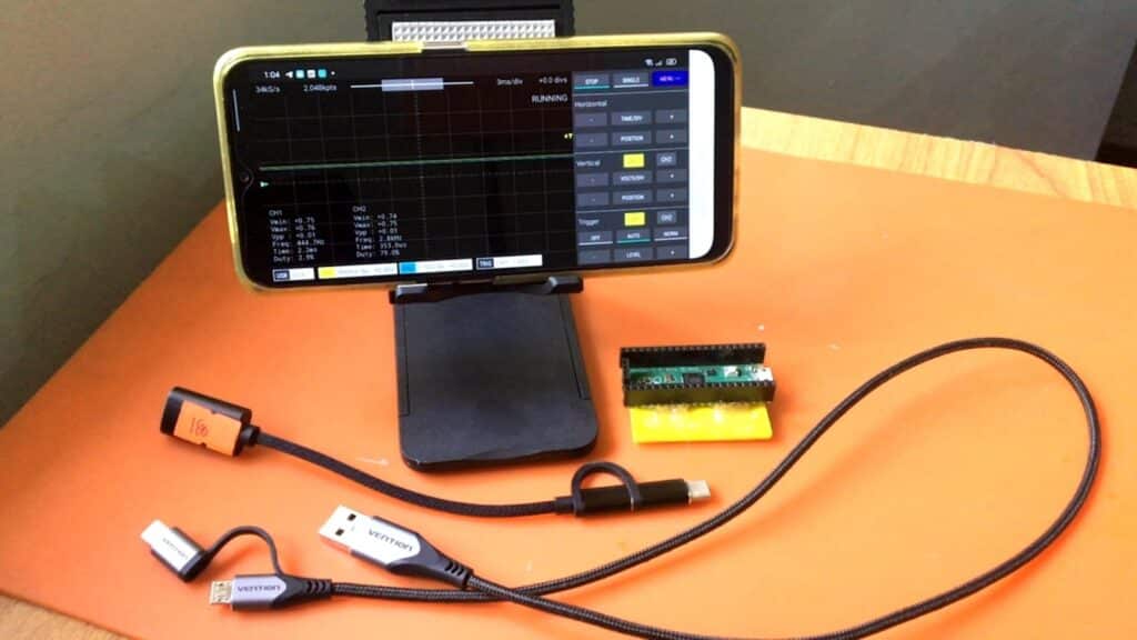
Basic materials needed to run the RPI oscilloscope
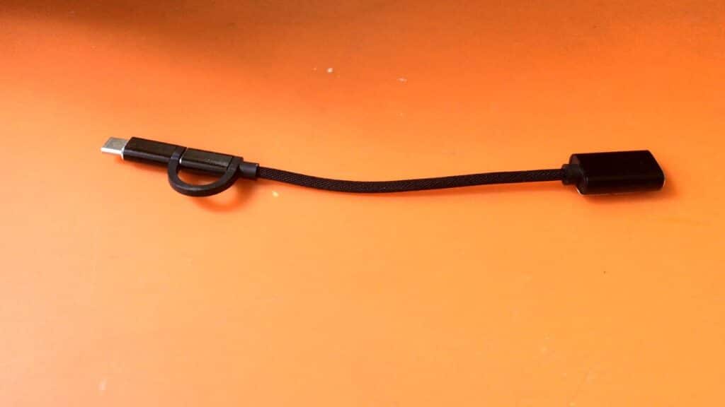
Here is an example USB OTG adapter that we used
The Oscilloscope App Explained
To make our lives easy, we’ll use a custom-made app. The app is called Scoppy from FHDM TECH. You can download the app from the Google Play Store for your Android devices. It is free to download. However, you can only use one oscilloscope channel for this. To use the second channel and unlock all other features, buy the app. It’s actually quite cheap.
Here are some pictures of the app in oscilloscope and logic analyzer mode:
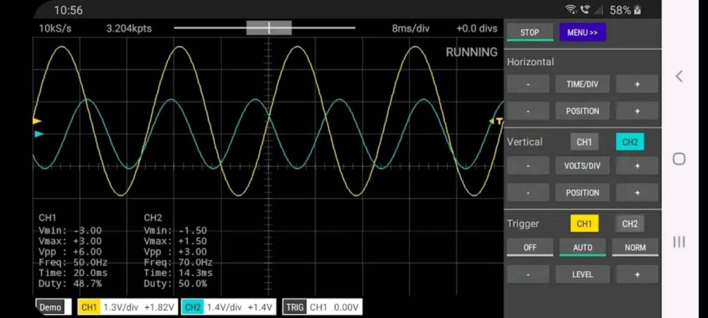
Using the 2-channel oscilloscope to capture sine waves
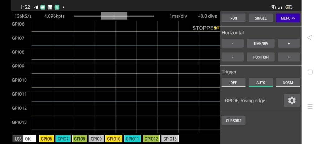
Using the 8-channel Logic Analyzer with all inputs enabled.
Scoppy can be used as an Oscilloscope, a Logic Analyzer, and a simple waveform generator.
As an oscilloscope, it can sample up to 500ksps and has two channels, namely Channels 1 and 2. It can display in X-Y and FFT modes. It can trigger in both channels, and you can adjust its levels in the software. You can change volts per div and time per div conveniently through the touch controls on the right side. You can enable real-time updates on the measurements of each signal through some settings. You can run the scope in single or continuous mode. With this, you’ll be able to trigger a single pulse and then capture a set of data.
The logic analyzer can have up to eight inputs of up to 25Msps per channel. Each input can be made the trigger source. You can change time per div settings in logic analyzer mode. You can run in single or continuous mode. There are onscreen cursors you can adjust for discrete measurements of time.
Lastly, the signal generator can generate square waves (100Hz – 1.25MHz) and pseudo-sine waves using PWM square waves along with a low-pass filter.
GPIO's Used
Here are the GPIO used in the RPI Pico Oscilloscope
GPIO 26 – CH1 ADC input
GPIO 27 – CH2 ADC input
GPIO 2 & 3 – CH1 attenuation selector
GPIO 4 & 5 – CH2 attenuation selector
GPIO 6-13 – Logic Analyzer Inputs.
GPIO 22 – Signal Generator output.
Note that you’ll need an analog front-end to be able to capture voltages greater than 3.3V in oscilloscope mode. Scoppy devised two GPIO pins per channel as inputs so that you can use these as voltage range selectors for your analog front-end circuit. Each of the oscilloscope channels will be assigned a voltage range set according to your analog front-end setting. The on-screen measurements will be adjusted accordingly.
The Signal generator can output square waves in 0-3.3V. It can also output a sine wave. However, it is done by varying the pulses of a square wave. Hence you will need a low-pass filter to get a proper sine wave output. Use a 1k resistor combined with a 0.1uf capacitor for this.
Conclusion
The RPI Pico can definitely be used as a medium sampling speed oscilloscope. It has the features of a microcontroller needed for this type of operation. You can use a ready-made Android app for this, available through Google Play. This will turn your Pico into a smart oscilloscope. The app is called Scoppy. The app’s features include a 2-channel oscilloscope, an 8-channel logic analyzer, and a signal generator. All of these functions were made to interface with the RPI Pico through a USB OTG cable adapter.


