A microcontroller with I2S output, such as the STM32 Black Pill, is an excellent choice for practicing Digital Audio programming. Read through this article to find out more.
Introduction
Previously, you’ve learned about the basics of I2S. Now, you can prepare a microcontroller to practice your acquired I2S knowledge. There are several chips today with an I2S peripheral as the trend in digital audio continues. Such chips like the ESP32, RPI Pico (through its PIO lines), and STM32s with Cortex-M processors, among others. Of particular interest is the STM32 Black Pill as this microcontroller development board has two dedicated I2S peripherals, perfect for learning I2S. Additionally, on the firmware side, no one beats STM32 Cube MX’s neat Graphical User Interface for setting up your microcontroller’s peripherals (such as I2S) quickly.
What You'll Need
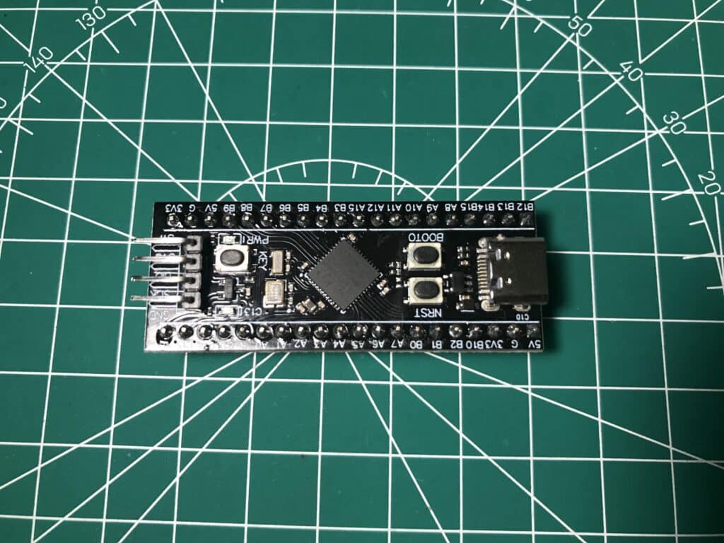
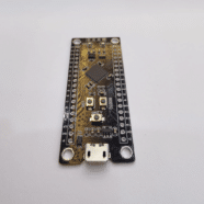
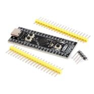
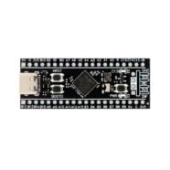
1. AN STM32 BLACKPILL.
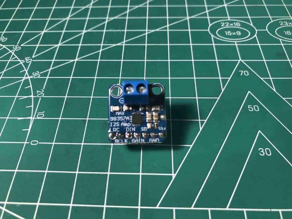
2. A MAX98357A I2S AUDIO DAC BREAKOUT BOARD OR SOMETHING SIMILAR.
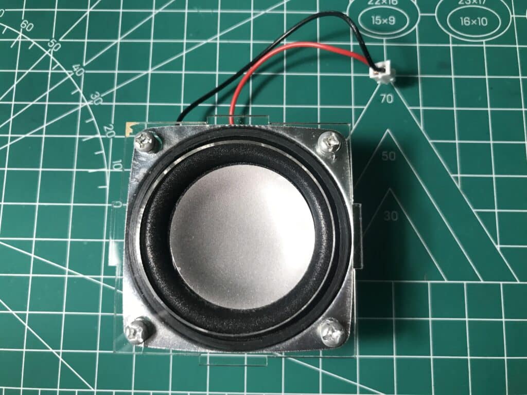
3. AN 8 OHM 3W AUDIO SPEAKER OR SOMETHING SIMILAR
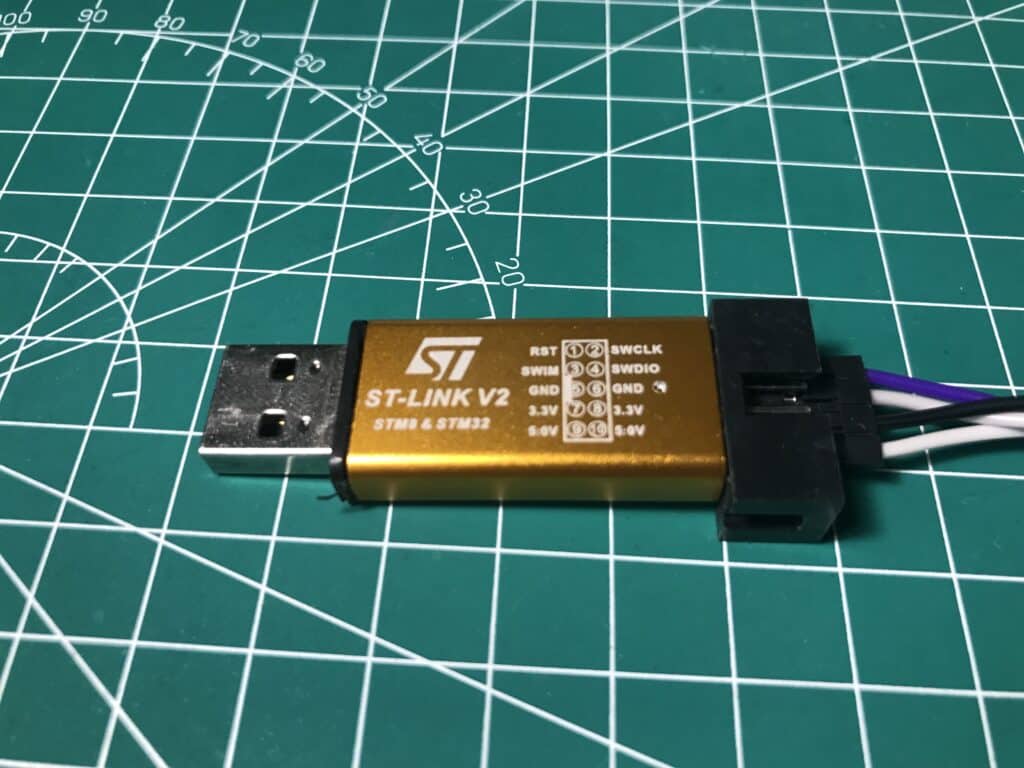
4. AN ST-LINK PROGRAMMER
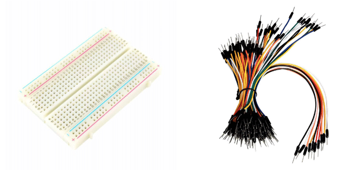
5. A BREADBOARD AND SOME CONNECTING WIRES
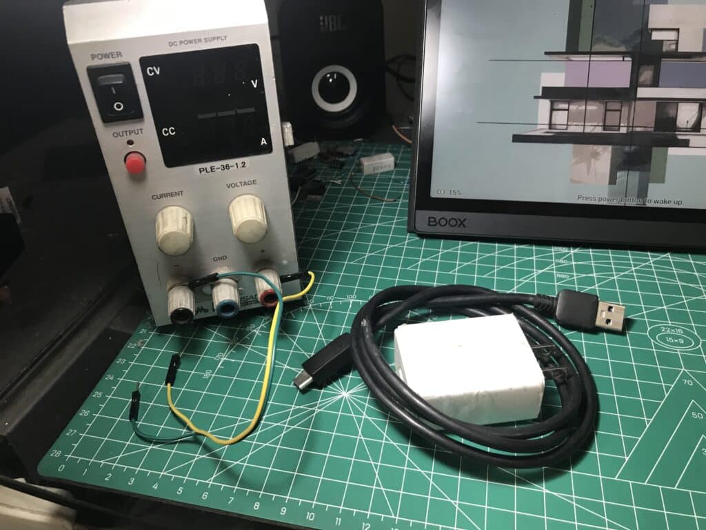
6. A 5V (1A) Power Supply or USB Type-C Supply
Prepare your BlackPill for the STM32Cube IDE Environment
The STM32CubeIDE tutorial should give you a primer on how to use STM32CUBE IDE. With this, you should be able to do basic setups on the GPIOs and peripherals of the Black Pill. Here, you can set up an LED port, a button port, and the I2S peripheral.
But first, a new project on the STM32Cube IDE must be set up.
Next, set up the main clock source. You’ll see below that the I2S peripheral has its own clock source.
Next, set up the LED port on PC13 and the Key_Button port on PA0. PA0 should be in pull-up mode.
Finally, set up your I2S peripheral. For the default values in the following tutorials, your I2S is in Half-Duplex Master Mode (since you only need to output I2S data to a Digital audio DAC). The communication protocol used is I2S Philips. The data and frame format are 16-bit data on a 16-bit frame (these parameters will depend on the bit characteristics of your audio stream). The audio frequency is arbitrarily set to 48kHz for now.
Save and Generate C Files
After this, you can continue with the actual connections on a breadboard.
Prepare Actual Circuit Connections
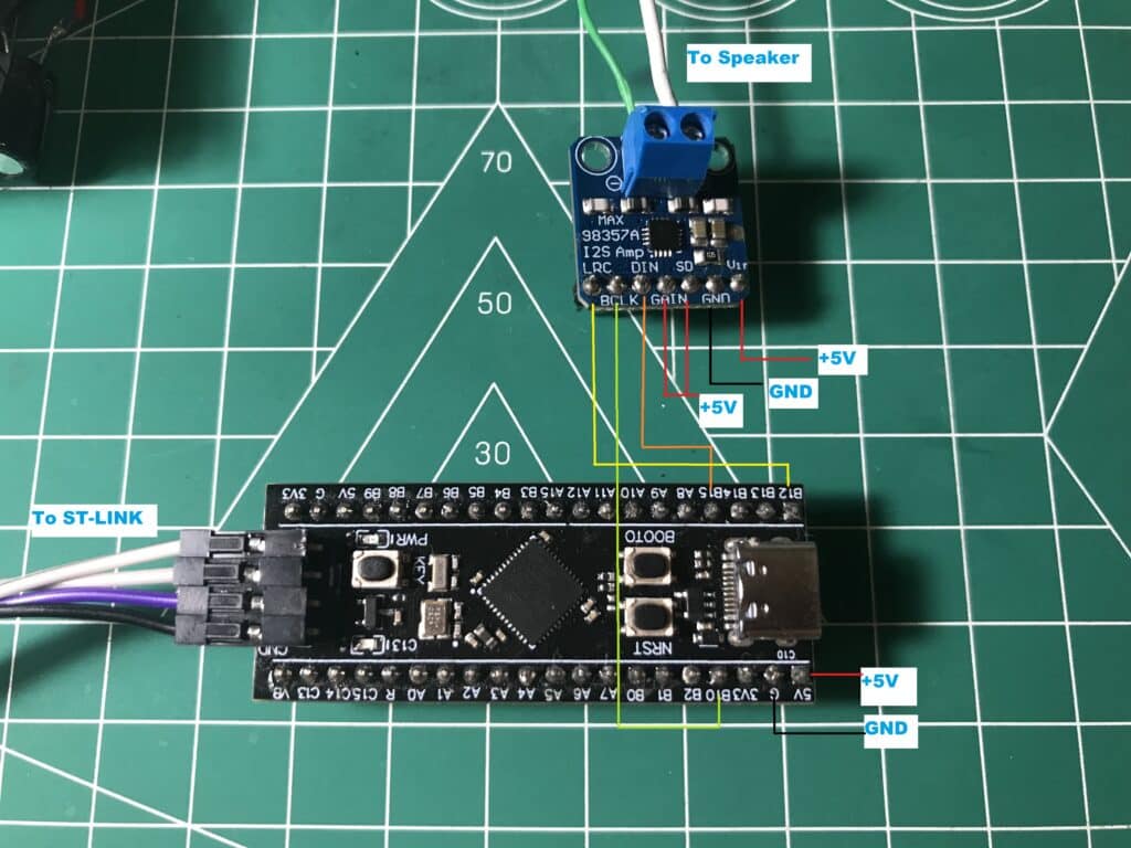
You can now connect the power and I2S lines of the MAX98357A I2S audio DAC breakout board. It is powered through +5V DC. The I2S lines of the breakout board connect to the BlackPill’s own I2S port.
MAX98357A DAC Pins
STM32 Black Pill Pins
Function
Vin
5V
+5V Vcc
GND
G
GND
SD
N/A
Shutdown (pull-up to Vcc)
GAIN
N/A
Gain (pull-up to Vcc)
DIN
B15
I2S Data
BLCK
B10
I2S Clock
LRC
B12
I2S WS (Word Select)
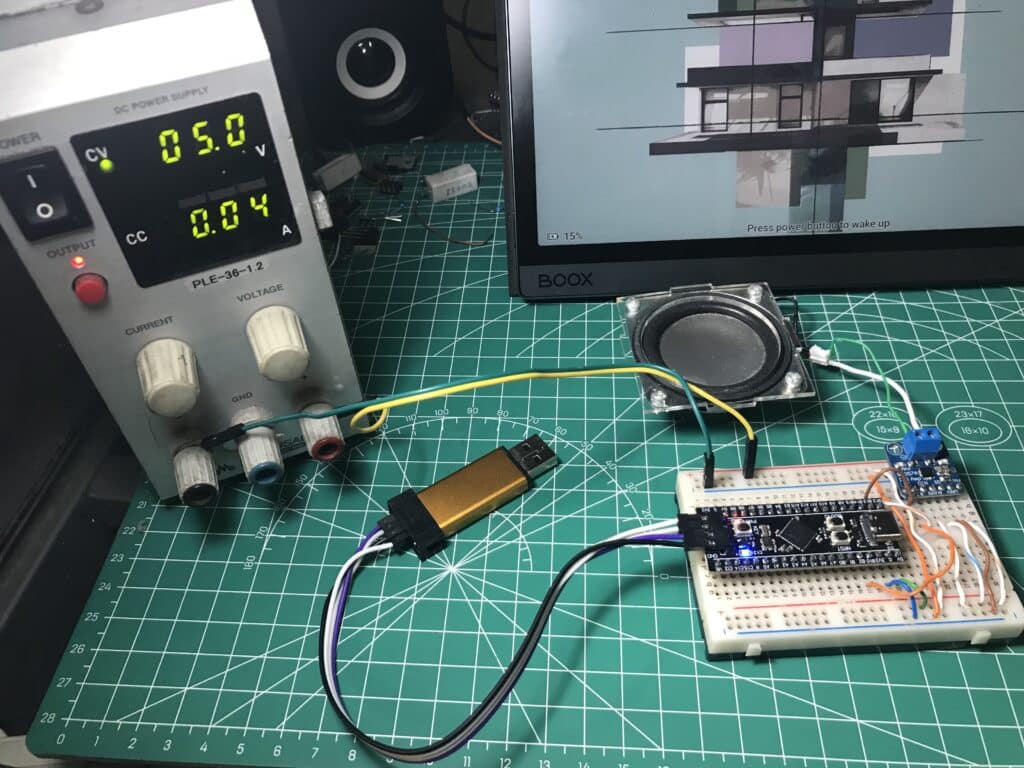
Here should be the final breadboard connections.
Note that, just in case, you may have to pull out the +3.3V line of the ST-Link when a +5V Vcc is applied to your circuit. This is so you have one voltage source powering your board.
ready for the Digital Audio Tutorials
You’re now up and ready to continue with the rest of the digital audio tutorials. Have fun!! 🙂