Read through this article if you want to simplify MOSFET protection from short circuits or overloads.
Introduction
You may have read Protecting MOSFETs from Short Circuits or Overloads last time. However, the method used in that article uses an OP-AMP circuit to know when the overload will happen. An advantage of this circuit is you can warn the user before the overload event occurs. This is because the OP-AMP circuit can always tell you your load current’s current reading.
However, if you don’t need to detect your load current every time and are constrained to use only discrete components, there is a simpler way of detecting the overload or short circuit event. This circuit will save you board space and is cost-effective. It may also respond faster since you don’t need an ADC to detect the overload condition.
BASIC Circuit DiagramS
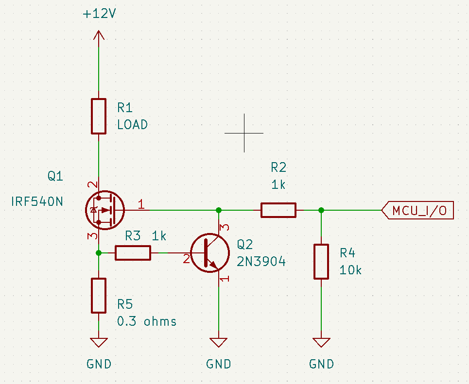
Basic Bipolar Current Limiter
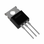
As in the previous blog, this circuit uses the basic bipolar current limiter topology. Q2 simply drives the gate voltage of Q1 to a level where current limiting happens. The current limit depends on the value of the Rsense resistor R5, 0.7V/R5.
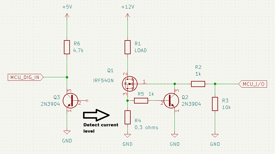
Additional Bipolar Over Current Detect Circuit
However, the bipolar current limiter above can only work briefly, especially if your MOSFET Q1 cannot handle the current limit. With this, you must detect this current limit and then have a microcontroller shut down the output. An additional bipolar transistor Q3 is added to detect such an event. Below, you’ll see the final circuit with an explanation.
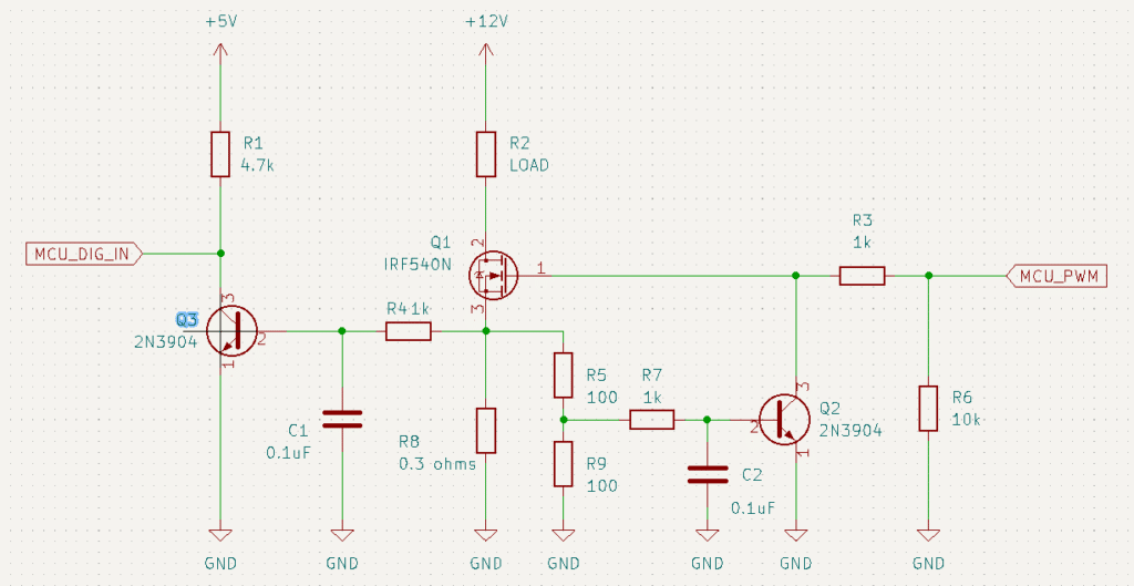
Final Circuit and Operation
Additional capacitors C1 and C2 are added as noise filters. The additional bipolar transistor Q3 cannot be added without further component calculations. Note that Q2 will also detect the overload event and clamp the load current to prevent further increasing it. Any two transistors are never the same. Hence, one transistor may detect the overload condition earlier than the other.
With this, you can place an allowance on your current detection scheme. Here, a voltage divider is placed in parallel with the sense resistor. The divider is made in such a way (depending on your preference) that Q2 will always detect the overload condition first and then clamp the current to a value a bit higher than without the voltage divider. After that, you’ll be sure that Q3 will detect this overload condition, reporting this event to your microcontroller. Your microcontroller will now shut down the gate of your MOSFET and, hence, the output.
Note that this protection scheme is voltage level triggered. With this, you can use this on PWM-based applications.
Testing and Debugging
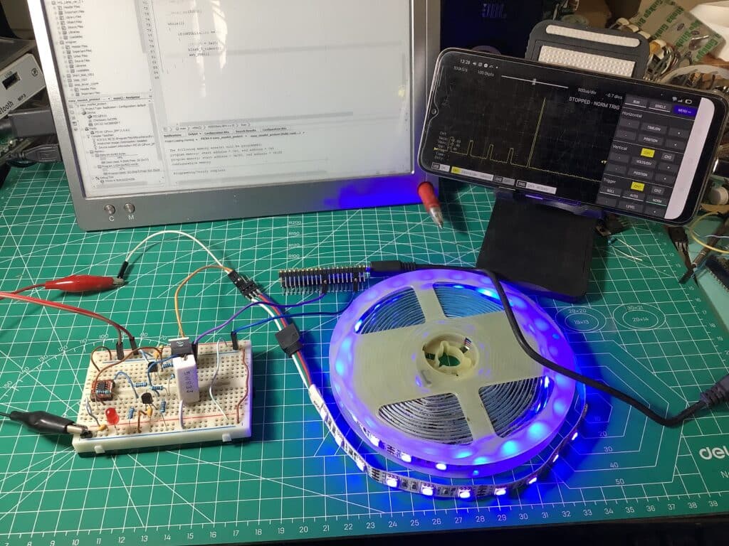
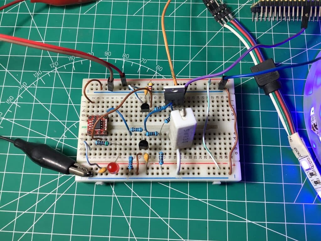
Here is a practical application of this circuit. Below is a DIY MOSFET driver for an LED strip. Since LED strips can be found outdoors, you may want to protect their driver circuit from shorts or overloads. An RPI Pico is used to plot the sense resistor’s voltage on the oscilloscope. A small microcontroller outputs a PWM waveform for the gate of the MOSFET, detects the overload on its GPIO pin, and then stops the PWM when it detects the overload. A red LED signals the overload. After a while, the PWM waveform is restored.
Circuit Setup
Video Demo of Short Circuit
Oscilloscope Capture of Current Limit
Conclusion
Here, MOSFET protection from short circuits or overloads was explained in detail. All you need are additional discrete components and a simple microcontroller.